
Dispersion-shifted single-mode fiber having low dispersion slope for large capacity transmission

a single-mode fiber and large-capacity technology, applied in the field of single-mode fibers, can solve the problems of limiting the augmenting of system capacity, s-band cannot be used for dwdm transmission, and inability to obtain complete compensation in side-band regions, etc., to achieve easy equilibration of dispersion slope, effective area and attenuation performance of fibers, and control the performance of fibers more precisely

Active Publication Date: 2005-10-04
YANGTZE OPTICAL FIBRE & CABLE CO LTD
View PDF7 Cites 19 Cited by
  • Summary
  • Abstract
  • Description
  • Claims
  • Application Information

AI Technical Summary

Benefits of technology

[0021]The advantageous effects of the invention are, as compared with the former structure, more waveguide structural parameters of the fiber, for example, ΔCore1%, ΦCore1, ΔCore2%, ΦCore2, ΔCore3%, ΦCore3, and the value of power α that determines the refractive index profile of Core1, can be adjusted. Therefore the design of multiple core segments has the capability of controlling the performances of the fiber more precisely, and the dispersion, dispersion slope, effective area, and attenuation performances of the fiber can be equilibrated easily.
[0022]By adjusting the refractive index profile of the fiber, the required values of dispersion, dispersion slope and larger effective area can be obtained, and said fiber possesses lower attenuation and excellent bending performance. According to the invention, the total dispersion of the fiber at 1550 nm is less than 0.060 ps / nm2·km, the zero-dispersion wavelength is less than 1420 nm, the effective area ranges from 55 μm2 to 65 μm2, the dispersion in the range of 1530 nm˜1565 nm is 5.0˜12.0 ps / nm2·km, the attenuation at 1550 nm is less than or equals to 0.22 dB / km. According to the method of bend resistance performance test, under the test condition of winding 100 turns on Φ 60 mm reel, the additional attenuation induced by bending is less than 0.05 dB at both 1550 nm and 1625 nm, under the test condition of winding 1 turn on Φ 32 mm reel, the additional attenuation induced by bending is less than 0.5 dB at both 1550 nm and 1625 nm. The attenuation in the whole 1530 nm˜1565 nm band is less than or equals to 0.23 dB / km. This is the optimal transmission window at the present time, for is corresponds to the range in which the gain of EDFA is flat, and high bit rate DWDM transmission may be carried out through it. In particular, because a depression structure is adopted in ΔClad3%, the cutoff wavelength is lowered and less than 1310 nm, so that single mode transmission through 1310 nm window may be performed simultaneously over the wide band non zero dispersion-shifted fiber of the invention.
[0023]The invention adopts more complex refraction index profile to realize the equilibrium among dispersion, dispersion slope, effective area and attenuation performances. In addition, in combination with the capability of precisely controlling the refractive index profile that is peculiar to PCVD process, the designed performance can be realized with high efficiency.

Problems solved by technology

Along with the development of the WDM technology, the influence on the system from the non-linear effects (for example, four-wave mixing, self-phase modulation, cross phase modulation, etc.) among the respective wavelengths limits the augment of the system capacity.
However, the zero dispersion point of the current non-zero dispersion-shifted fiber is within S-band, so that S-band cannot be used for DWDM transmission.
Thus, when making management of dispersion using dispersion compensation technique, except in central wavelength region, the complete compensation cannot be obtained in side band regions.
This problem does not affect greatly a system which transmission rate is less than 10 Gbits / s, however, for a 40 Gbits / s high-speed transmission system that requires precisely managing dispersion, the high dispersion slope becomes a serious problem.
However, because the fiber section has a fewer number of segments, its structure is rather simple, and the parameters for controlling the refractive index profiles of the core segments are relatively fewer, so that to precisely control the parameters of fiber is difficult.
Therefore, to equilibrate and control the dispersion, dispersion slope, effective area, and attenuation performances is difficult.
In a WDM system, if the transmission path has large dispersion slope, then the difference of dispersion value between wavelengths increases, and the transmission performance is deteriorated as a whole.

Method used


Image

  • Dispersion-shifted single-mode fiber having low dispersion slope for large capacity transmission
  • Dispersion-shifted single-mode fiber having low dispersion slope for large capacity transmission
  • Dispersion-shifted single-mode fiber having low dispersion slope for large capacity transmission

Examples


embodiment 1

[0033

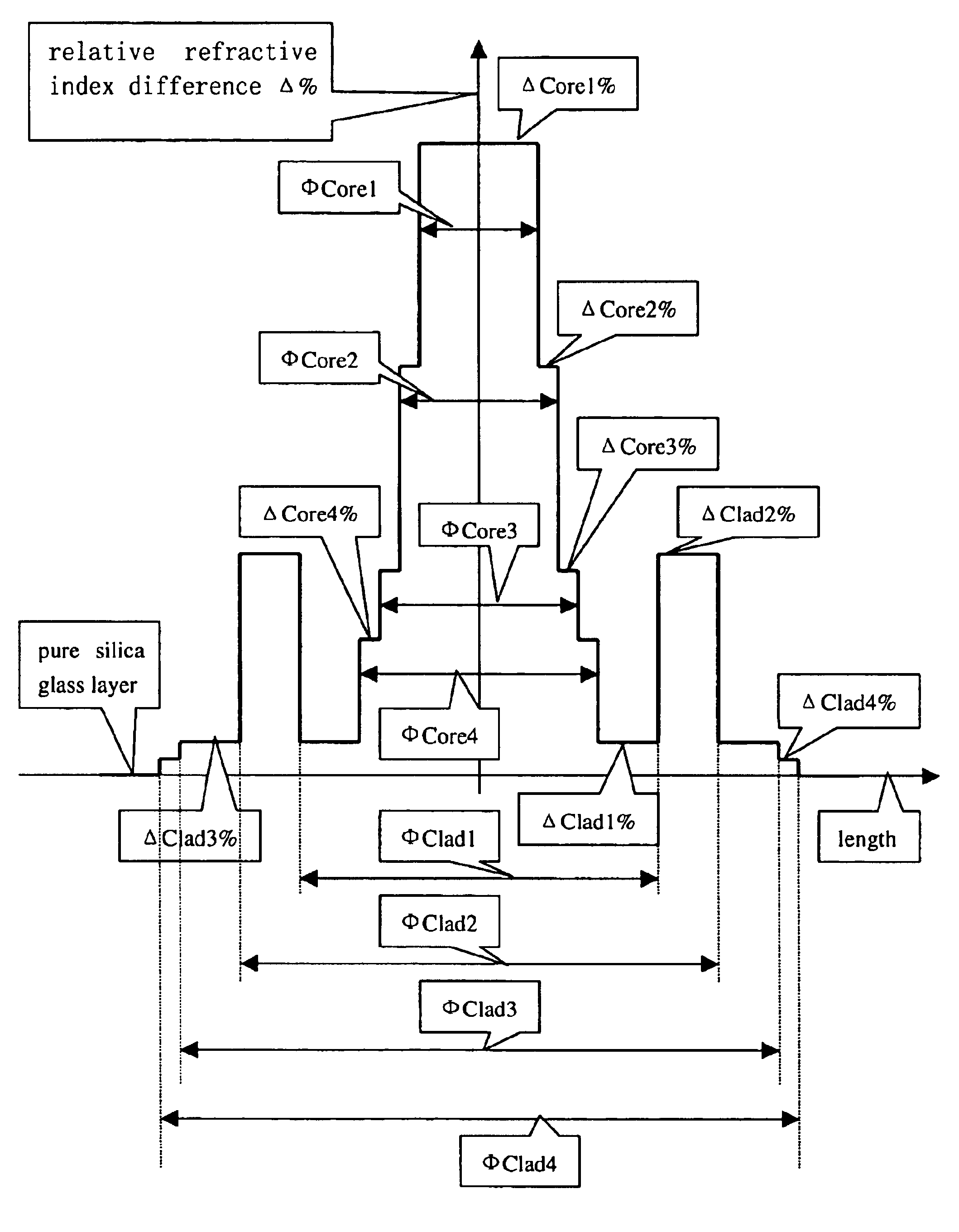
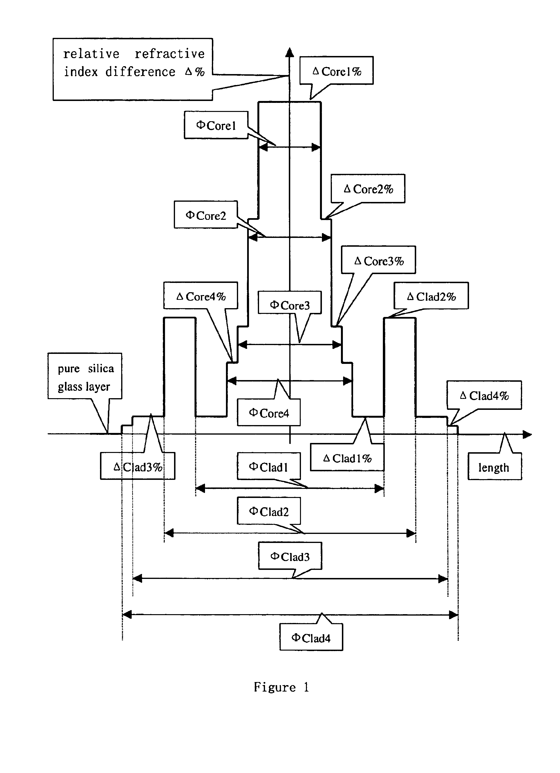
[0034]The parameter set for relative refractive index difference profiles shown in FIG. 1 are listed as follows:

[0035]The parameters of the respective core segments are:

[0036]First core segment Core1:[0037]ΔCore1% is about 0.64, ΦCore1 is about 3.0 μm

[0038]Second core segment Core2:[0039]ΔCore2% is about 0.42, ΦCore2 is about 4.1 μm

[0040]Third core segment Core3:[0041]ΔCore3% is about 0.21, ΦCore3 is about 7.5 μm

[0042]Fourth core segment Core4:[0043]ΔCore4% is about 0.15, ΦCore4 is about 9.0 μm

[0044]The parameters of the respective cladding segments are:

[0045]First cladding segment Clad1:[0046]ΔClad1% is about 0.04, ΦClad1 is about 15.0 μm

[0047]Second cladding segment Clad2:[0048]ΔClad2% is about 0.25, ΦClad2 is about 21.0 μm

[0049]Third cladding segment Clad3:[0050]ΔClad3% is about 0.04, ΦClad3 is about 27.0 μm

[0051]Fourth cladding segment Clad4:[0052]ΔClad4% is about 0.02, ΦClad4 is about 31.0 μm

[0053]The outmost cladding segment is a pure silica glass layer.

[0054]The performa...

embodiment 2

[0064

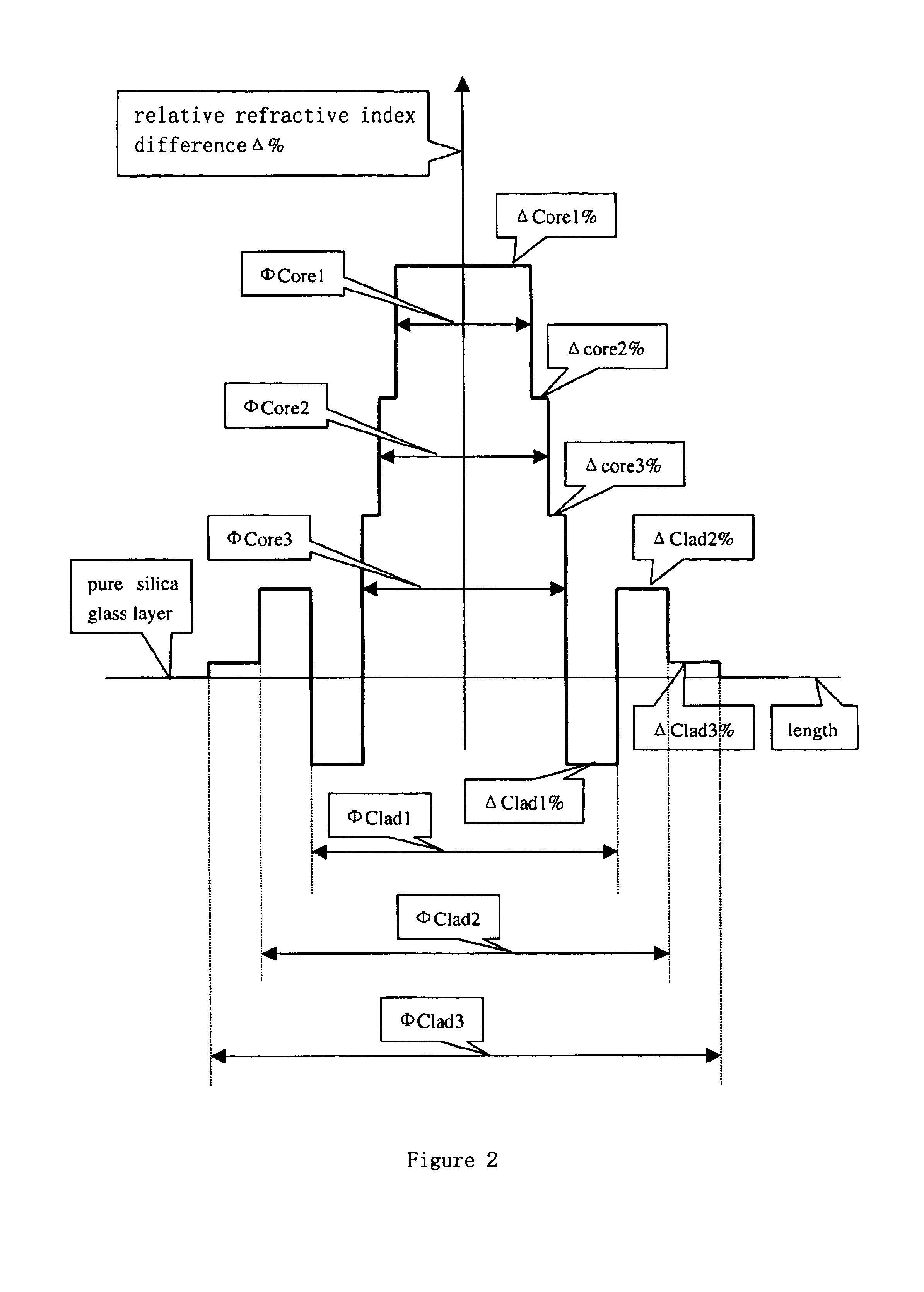
[0065]The parameter set for relative refractive index difference profiles shown in FIG. 2 are listed as follows:

[0066]The parameters of the respective core segments are:

[0067]First core segment Core1:[0068]ΔCore1% is about 0.42, ΦCore1 is about 4.6 μm

[0069]Second core segment Core2:[0070]ΔCore2% is about 0.35, ΦCore2 is about 6.0 μm

[0071]Third core segment Core3:[0072]ΔCore3% is about 0.28, ΦCore3 is about 7.1 μm

[0073]The parameters of the respective cladding segments are:

[0074]First cladding segment Clad1:[0075]ΔClad1% is about −0.10, ΦClad1 is about 11.5 μm

[0076]Second cladding segment Clad2:[0077]ΔClad2% is about 0.18, ΦClad2 is about 16.2 μm

[0078]Third cladding segment Clad3:[0079]ΔClad3% is about 0.02, ΦClad3 is about 29.0 μm

[0080]Fourth cladding segment is a pure silica glass layer.

[0081]The performances of the obtained fiber are the follows:

[0082]Effective area at 1550 nm: 64 μm2,

[0083]Zero-dispersion wavelength: 1395 nm,

[0084]Dispersion at 1550 nm: 7.4 ps / nm·km,

[0085]Di...

embodiment 3

[0091

[0092]The fiber of Embodiment 3 has two negative relative refractive index differences in its cladding segments. The parameter set for said relative refractive index difference profiles shown in FIG. 3 are listed as follows:

[0093]The parameters of the respective core segments are:

[0094]First core segment Core1:[0095]ΔCore1% is about 0.42, ΦCore1 is about 4.6 μm

[0096]Second core segment Core2:[0097]ΔCore2% is about 0.35, ΦCore2 is about 6.0 μm

[0098]Third core segment Core3:[0099]ΔCore3% is about 0.28, ΦCore3 is about 7.1 μm

[0100]The parameters of the respective cladding segments are:

[0101]First cladding segment Clad1:[0102]ΔClad1% is about −0.08, ΦClad1 is about 12.5 μm

[0103]Second cladding segment Clad2:[0104]ΔClad2% is about 0.18, ΦClad2 is about 18.1 μm

[0105]Third cladding segment Clad3:[0106]ΔClad3% is about −0.08, ΦClad3 is about 29.0 μm

[0107]Fourth cladding segment is a pure silica glass layer.

[0108]The performances of the obtained fiber are the follows:

[0109]Effective are...


PUM


Abstract

The invention relates to a low dispersion slope dispersion-shifted single-mode fiber for large capacity transmission comprising a core and a cladding. Said fiber is characterized in that said core has three to five core segments having different refractive index profiles, and said cladding has four to six cladding segments. The total dispersion slope of said fiber at 1550 nm is less than 0.060 ps / nm2·km, the zero dispersion wavelength is less than 1420 nm, the effective area ranges from 55 μm2 to 65 μm2, and the dispersion in the region of 1530 nm˜1565 nm ranges from 5.0 ps / nm2·km to 12.0 ps / nm2·km. The fiber has low dispersion slope, moderate dispersion, low attenuation, and excellent bend resistance performance. It is suitable for a high-speed (10 Gbits / s and 40 Gbits / s), large capacity, and long distance DWDM system. Therefore, not only the non-linear problem that fazes high-speed communication is solved effectively, but also the DWDM transmission at 10 Gbits / s can be realized within a wider wavelength range. In addition, low dispersion slope is advantageous for comprehensive management of dispersion, so that the requirement for long distance non-electric relay can be fulfilled.

Description

CROSS-REFERENCE TO RELATED APPLICATIONS[0001]This application claims priority to Chinese Application No. 03118463.4, filed on Jan. 14, 2003, the contents of which is hereby incorporated in its entirety by reference.BACKGROUND OF THE INVENTION[0002]I. Field of the Invention[0003]The present invention relates to a single-mode fiber designed for large capacity transmission system. The fiber has low dispersion slope, moderate dispersion, low attenuation, and excellent bend resistance performance. It is suitable for a high speed (10 Gbits / s and 40 Gbits / s), large capacity, long distance dense wavelength division multiplex (DWDM) system, and all the S, C, and L bands of the fiber can be used for DWDM transmission.[0004]II. Description of the Related Art[0005]Since the middle of nineties of the twentieth century, along with the developments of the erbium-doped fiber-amplifier (EDFA) and wavelength division multiplex (WDM) technology, the fiber communication enters its unprecedented high-sp...

Claims


Application Information

Patent Timeline
IPC IPC(8): G02B6/036G02B6/02
CPCG02B6/02009G02B6/02242G02B6/03688
Inventor ZHANG, SHUQIANGHAN, QINGRONGCAO, YUQINGWANG, TIEJUNMATAI, RAADJLUO, JIE
Owner YANGTZE OPTICAL FIBRE & CABLE CO LTD
Learn More