

Vehicle air conditioner with reduced fuel consumption of vehicle engine
- Summary
- Abstract
- Description
- Claims
- Application Information
AI Technical Summary
Benefits of technology
Problems solved by technology
Method used
Image

Examples
first embodiment
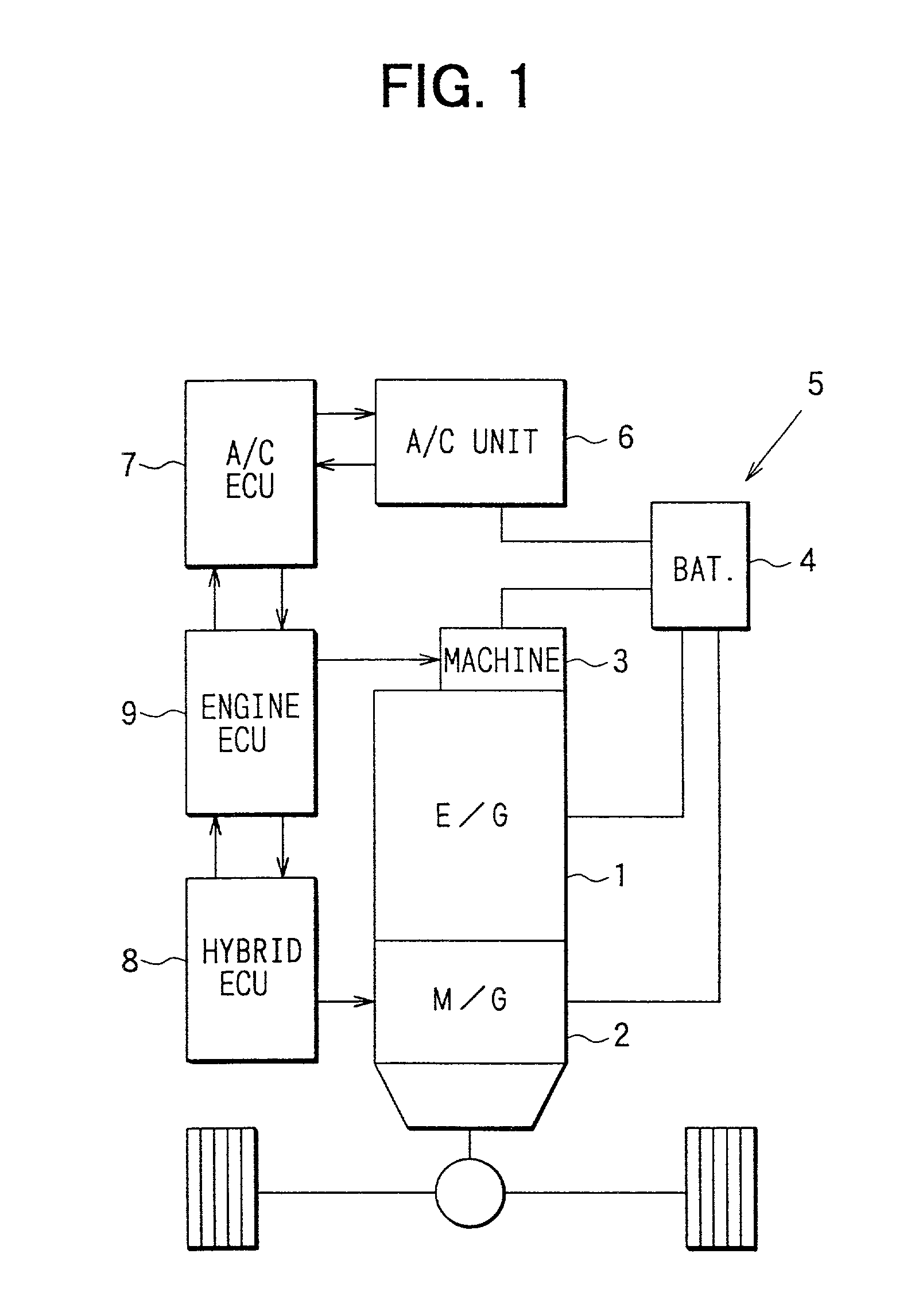
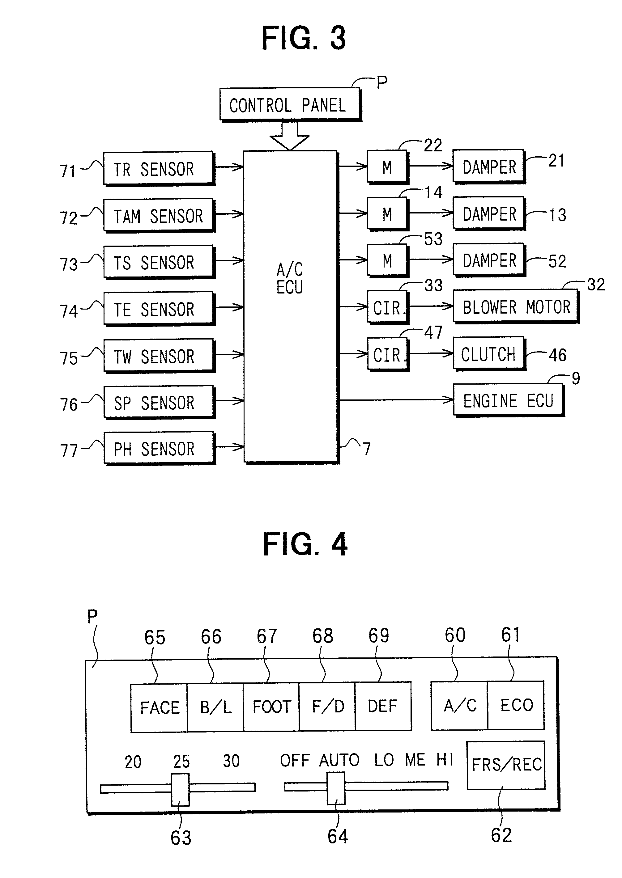
[0052] Next, a control system will be now described based on FIGS. 1, 3 and 4. Into the air conditioning ECU 7, communication signals output from the engine ECU 9, switch signals from operation switches of a control panel P provided on a front surface within the passenger compartment and sensor signals from various sensors are input.
[0053] Specifically, as shown in FIG. 4, the switches provided on the control panel P are an air conditioning (A / C) switch 60, an economy (ECO) switch 61, an air-introduction mode selecting switch 62 for switching an air introduction mode, a temperature setting lever 63 for setting the temperature of the passenger compartment at a desired temperature, an air amount setting lever 64 for setting an air amount blown from the centrifugal fan 31, and an air outlet mode setting switches 65-69 for selectively setting an air outlet mode.
[0054] The air conditioning switch 60 is an air conditioning operation switch for setting a cooling mode based on mainly the p...
third embodiment
[0106] That is, in the third embodiment, when the second engine operation request signal (second E / G ON signal) is received at step S26 in FIG. 8, the control at step S51 is performed after the controls at steps S27 and S28 are performed. That is, at step S51, 0-zone of a low humidity area, 1-zone of a middle humidity area and 2-zone of a high humidity area are set, and a zone determination is performed based on the relative humidity of the windshield 5a in accordance with the characteristic view of step S51 pre-stored in the ROM. When the relative humidity RHW of the windshield 5a is increased to be larger than 80%, the zone state is changed from 0-zone to 1-zone. Further, when the relative humidity RHW of the windshield 5a is increased to be larger than 90%, the zone state is changed from 1-zone to 2-zone. On the other hand, when the relative humidity RHW of the windshield 5a is decreased to 80%, the zone state is changed from 2-zone to 1-zone. Further, when the relative humidity ...
sixth embodiment
[0119] the air amount ratio blown from the defroster opening 18 is controlled based on the relative humidity RHW which is mainly related to the fogging degree of the windshield 5a, and the air amount ratio from the defroster opening 18 is increased when the windshield 5a is readily fogged. Therefore, defrosting effect of the windshield 5a can be effectively improved.
[0120] A seventh preferred embodiment of the present invention will be now described with reference to FIG. 20. In the seventh embodiment, the control of step S31 in the first embodiment or the second embodiment is changed to the control of step S31a in FIG. 20. In the seventh embodiment, the other parts are similar to those of the above-described first or second embodiment.
[0121] Specifically, at step S31a, the set values of the relative humidity RH25 of the passenger compartment, for switching the second target post-evaporator temperature TE2, are set to be similar to those at step S28. That is, as shown in the charac...
PUM
 Abstract
Description
Claims
Application Information