Display apparatus and back light unit to be used therefor

Inactive Publication Date: 2009-12-10
HITACHI LTD
View PDF8 Cites 79 Cited by
  • Summary
  • Abstract
  • Description
  • Claims
  • Application Information

AI Technical Summary

Benefits of technology

[0009]According to the present invention, it is capable of making a thin-type display apparatus, with a larger screen, as

Problems solved by technology

In the side-light system, because a light source is arranged at the end of the view screen in a focused way, radiation or cooling of heat from the light source, control of illuminance of the light source, for example, in response to an image signal, and scale-up are more difficult as compared with the direct backlight.
On the other hand, in the direct backlight, because the number of light sources to be used increases as c

Method used


Image

  • Display apparatus and back light unit to be used therefor
  • Display apparatus and back light unit to be used therefor
  • Display apparatus and back light unit to be used therefor

Examples


embodiment 1

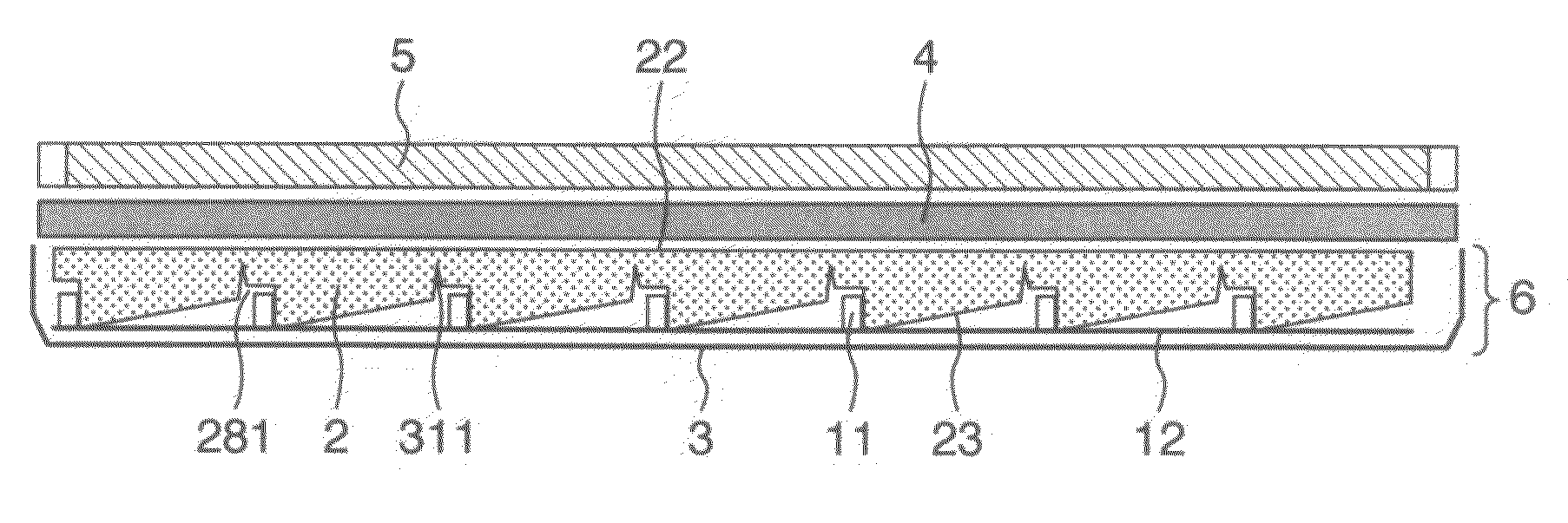
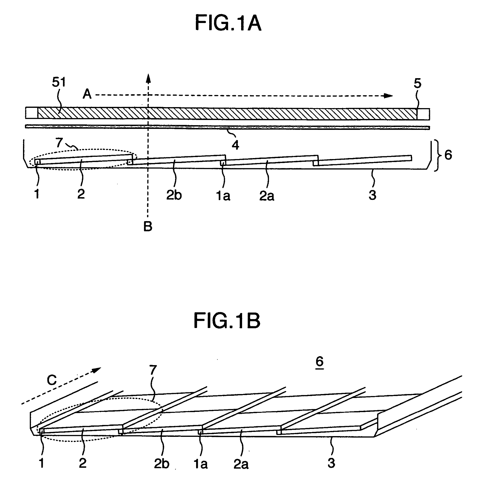
[0025]FIGS. 1A and 1B shows an example of a configuration of an image display apparatus relevant to a first embodiment of the present invention. FIG. 1A is a cross-sectional view of a horizontal direction of the liquid crystal panel 5, of a liquid crystal image display apparatus including the liquid crystal panel 5 and the back light unit 6, and also FIG. 1B shows a perspective view of such a back light unit 6. In this drawing, the arrow mark A is a direction parallel to the display face of the liquid crystal panel 5, shows a horizontal direction of the liquid crystal panel 5. In addition, the arrow mark B is a direction orthogonal to the display face of the liquid crystal panel 5, and the arrow mark C is a direction parallel to the display face of the liquid crystal panel 5, shows a vertical direction of the liquid crystal panel 5.

[0026]The image display apparatus relevant to the present embodiment, as shown in FIG. 1A, is provided with the liquid crystal panel 5 as a passive displ...

embodiment 2

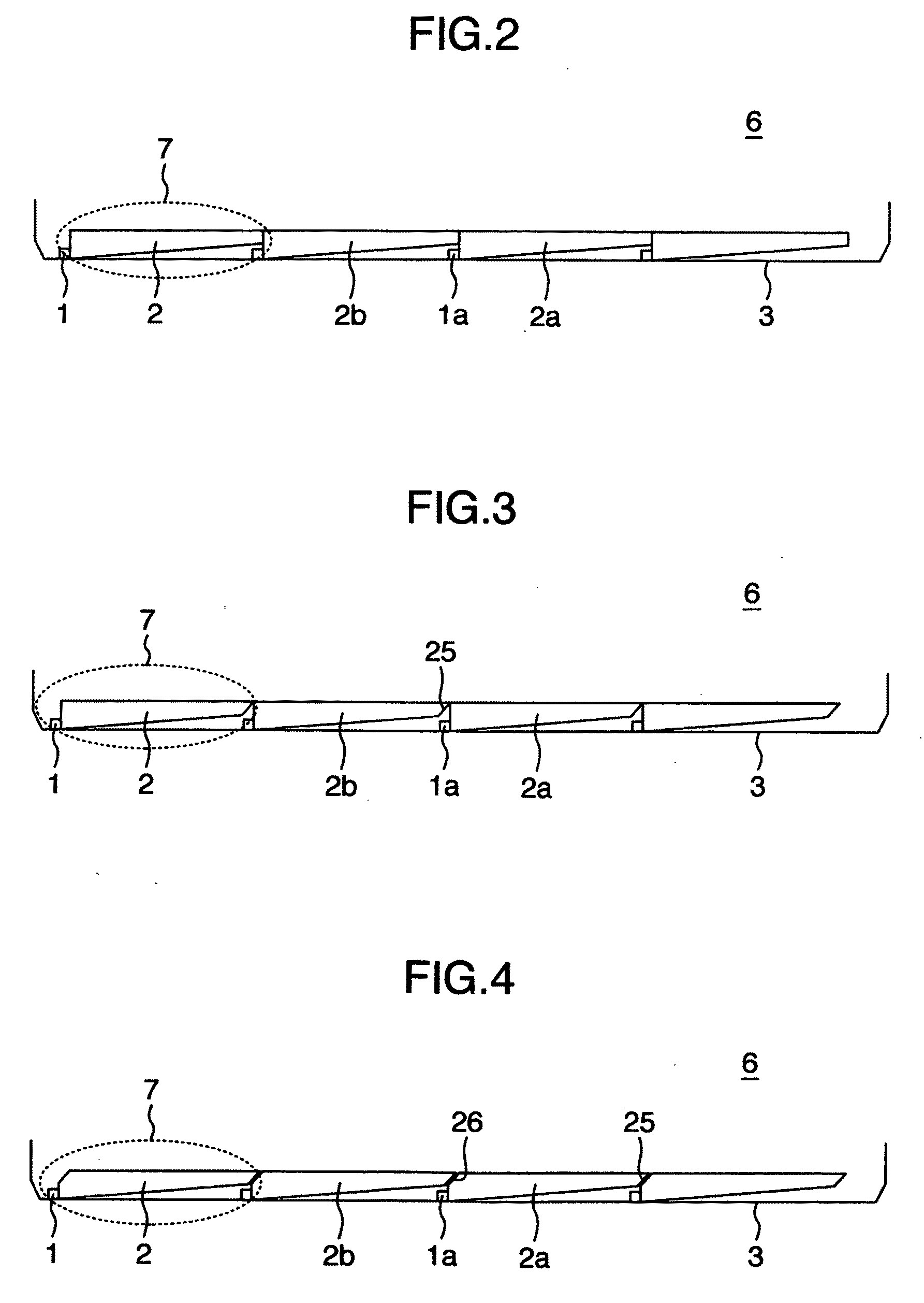
[0044]Explanation will be given below on a second embodiment of the present invention with reference to FIGS. 2 to 4.

[0045]In the above first embodiment, each of the light source units 7 was arranged in an inclined state, however, in the second embodiment shown in FIG. 2, each of the light source units 7 is arranged, so that the light emitting surfaces of a plurality of optical waveguides 2 are aligned on nearly the same plane. Also, in the present embodiment, to make possible the above overlap, that is, so that the light source 1a of a certain light source unit 7 can be arranged at the part lower than the reflecting face of the optical waveguide 2b of other light source unit 7, such shape is taken that the reflecting face of the optical waveguide 2 of each of the light source units 7 is inclined against the light emitting surface or the main plane of the chassis 3, and thickness of each of the optical waveguides 2 gradually decreases from the light incidence surface toward the end ...

embodiment 3

[0050]Explanation will be given below on a third embodiment of the present invention with reference to FIG. 5.

[0051]In this embodiment, as shown in FIG. 5A, the end part inclined face 25 is provided at the end part of the optical waveguide 2, as well as all of the reflecting faces are made parallel to the light emitting surface at the vicinity of the end part inclined face 25, without inclining at the light emitting surface. Still more, a step having shape corresponding to shape of the end part including the end part inclined face 25 is provided at the vicinity of the light incidence surface of the optical waveguide 2, so as to provide a shape to put on the end part of the adjacent optical waveguides 2. For example, at the vicinity of the injecting face of the optical waveguide 2a, a step having shape, which is capable of putting on a part of the end part of the optical waveguide 2b, is formed, which makes positioning of a plurality of the optical waveguides 2 easy. Therefore, becau...


PUM


Abstract

A back light unit includes a light source unit combined with an optical waveguide having translucency to guide a light of light source in a direction of liquid crystal panel, and a chassis for holding or supporting the light source unit. The optical waveguide is formed in plate-like shape, a face opposing to the back face of liquid crystal panel is used as a light emitting surface, a face opposing to the chassis is used as a reflecting face for reflecting a light, one of a plurality of side faces adjacent to light emitting surface and reflecting face is used as a light incidence surface where a light from the light source is injected. The light source unit is arranged in multiple in a horizontal direction or a vertical direction of the liquid crystal panel, in the back face side of the liquid crystal panel.

Description

INCORPORATION BY REFERENCE[0001]The present application claims priorities from Japanese applications JP2008-150057 filed on Jun. 9, 2008, JP2009-075375 filed on Mar. 26, 2009, the contents of which are hereby incorporated by reference into this application.BACKGROUND OF THE INVENTION[0002]The present invention relates to a display apparatus provided with a back light unit for irradiating a light, for example, onto a liquid crystal panel.[0003]In a display apparatus using a passive element such as, for example, liquid crystal panel as a display device, mainly the following two systems are known as a system of a back light unit for irradiating a light onto the liquid crystal panel. One is a side-light system for irradiating a light from either side or up and down end part of the liquid crystal panel, and for example, one described in JP-A-2008-103162 is known. The other is a direct backlight for irradiating a light from the back face of the liquid crystal panel, and for example, one d...

Claims


Application Information

Patent Timeline
IPC IPC(8): G02F1/13357G02F1/1333
CPCG02B6/002G02B6/008G02B6/0068
Inventor MURATA, SEIJIOUCHI, SATOSHI
Owner HITACHI LTD
Why Eureka
Try Eureka