

Back light for liquid crystal display
a liquid crystal display and back light technology, applied in the field of back lights, can solve the problems of limited light forming, limited thin sized back lights, low luminance, etc., and achieve the effect of reducing the sustain voltage of luminescent lamps, uniform luminance, and reducing the length of luminescent lamps
- Summary
- Abstract
- Description
- Claims
- Application Information
AI Technical Summary
Benefits of technology
Problems solved by technology
Method used
Image

Examples
first embodiment
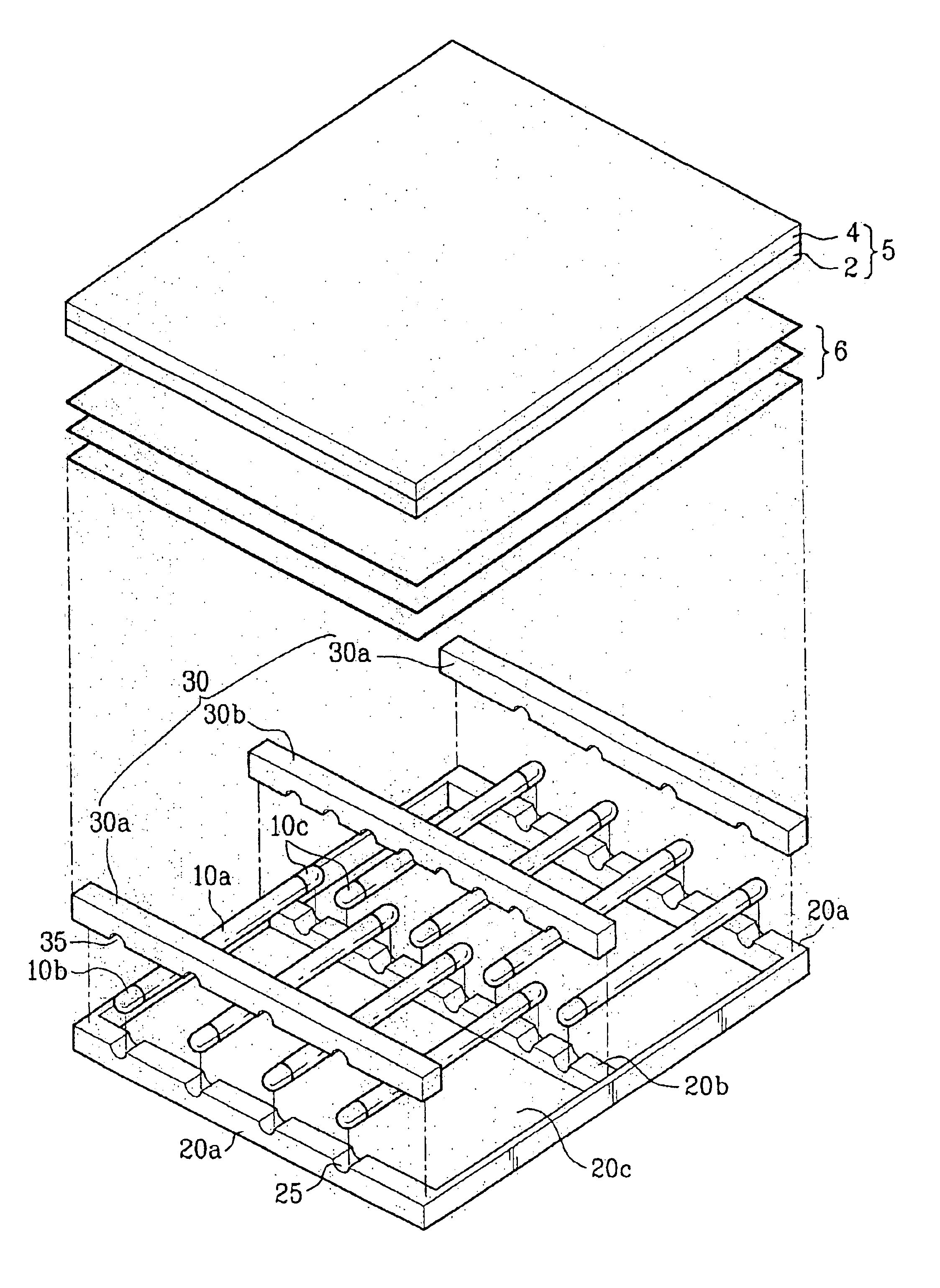
[0042]the present invention will be described with reference to FIGS. 5A to 5C.
[0043]As shown in FIG. 5A, a hole or recess 25 is formed in the first support members 20a and the second support member 20b which constitute the first case 20. The luminescent lamp 10 is received in the hole 25. Here, the hole or recess 25 is formed entirely through the first support members 20a and the second support member 20b such that the electrodes 10b and 10c of the lamp are exposed.
[0044]Also, a second case 30 may be formed on the first case 20 so as to fix the first case 20 and the luminescent lamp 10. The second case 30 includes first bars 30a which fix one electrode 10b of the luminescent lamp 10 to the first support members 20a, and a second bar 30b which fixes the other electrode 10c of the luminescent lamp 10 to the second support member 20b. A hole or recess 35 is formed in the first and second bars 30a and 30b, similar to the hole or recess 25. Also, the first and second bars 30a and 30b ma...
second embodiment
[0048]FIG. 6 is a plane view of a back light according to the present invention.
[0049]The second embodiment of the present invention is identical to the first embodiment except that the second support member 20b is formed at the center of the first case 20 in a zigzag pattern, and not a straight line. Therefore, the same reference numbers will be used throughout the drawings to refer to the same or like parts, and their description will be omitted.
[0050]In more detail, the luminescent lamps 10 are arranged so that the electrodes 10c supported by the second support member 20b are arranged in a zigzag pattern, and not a straight line.
[0051]The luminescent lamps 10 are arranged as described above, so as to minimize uneven luminance that may occur at the center portion of the back light.
[0052]Preferably, as shown in FIG. 7, it is intended that the luminescent lamps 10 are arranged to place boundary portions between the tubes 10a and the electrodes 10c of the luminescent lamps on the sam...
PUM
| Property | Measurement | Unit |
|---|---|---|
| length | aaaaa | aaaaa |
| voltage | aaaaa | aaaaa |
| sizes | aaaaa | aaaaa |
Abstract
Description
Claims
Application Information