Local coil unit for a magnetic resonance apparatus

a magnet resonance and local coil technology, applied in the field of local coil units for magnet resonance apparatuses, can solve the problems of inhomogeneous b1 field distribution, false measurement, and undesired dependence of image contrast, and achieve the effects of convenient laying of the device on the patient, convenient handling, and weight saving

Inactive Publication Date: 2006-02-21
SIEMENS HEALTHCARE GMBH
View PDF5 Cites 24 Cited by
  • Summary
  • Abstract
  • Description
  • Claims
  • Application Information

AI Technical Summary

Benefits of technology

[0019]A further advantage of the invention is that, because the local coil unit is used in the vicinity of the body, the dielectric material is automatically positioned correctly. For example, the examination of the upper body is undertaken with a body coil unit lying on the body that receives magnetic resonance signals from the area to be examined. B1 field minima in the heart area are compensated in the optimum way by the dielectric material in the coil housing which lies on the patient's chest. The spinal column unit is particularly suitable for compensating for B1 field minima in the area of the spinal column musculature. This is because, for MR examinations the patient generally is lying on his or her back on a patient table into which the spinal column unit is integrated. Preferably the dielectric material is built into the cover of the spinal column unit in this case.
[0020]In an embodiment of the local coil unit in accordance with the invention the material has a dielectric value εr greater than 50, preferably greater than 100 and a dielectric loss factor tan δ of less than 2.5×10⁻², preferably less than 1×10⁻³.
[0021]An advantage of placing the material close to the inhomogeneity is that little dialectic material is needed to generate a sufficient displacement current with the corresponding magnetic field.
[0022]In a further embodiment of the local coil unit the material is embodied as a surface that is as enclosed as possible, which is preferably 100–300 cm2 in size. The dimensions of this surface roughly correspond to the dimensions of the eddy currents that lead to B1 field suppression.
[0023]In a further embodiment of the local coil unit the enclosed surface has a cutout. This has the advantage of allowing a normal coil housing to be used for the local coil unit, most of these housings have cutouts to save weight, for easier handling and to facilitate laying them on a patient.
[0024]Further advantages of the invention are the at least partial reduction of electrical coupling of local coil unit with a whole body coil unit, and an extensive screening of the local coil unit from electrical field components. The latter has direct additional advantages such as a reduction of noise during reception, and an improved electrical decoupling of a receiver coil unit from the surrounding body transmission coils. In the reception mode this leads to an increase of the signal level and in the transmission mode this leads to a decoupling between the transmission and reception antenna.

Problems solved by technology

Variations in space and time in the field strength of the exciting B1 field lead to undesired changes in the received magnetic resonance signal that can falsify the measurement result.
Thus the spatial distribution of the amplitude of the B1 field typically causes an undesired dependence of the image contrast on the spatial position.
Although magnetic resonance devices with basic magnetic fields greater than 1.5 T basically make images with better resolutions possible, conventional types of these magnetic resonance devices have the disadvantage of increasing the inhomogeneous B1 field distributions, which stem for example from radio-frequency eddy currents in the subject under examination.
Despite these efforts in the prior art, the inhomogeneities in the excitation field cannot be sufficiently compensated in all cases.
However to date there has been no configuration which functions universally for each body and each position.

Method used


Image

  • Local coil unit for a magnetic resonance apparatus
  • Local coil unit for a magnetic resonance apparatus
  • Local coil unit for a magnetic resonance apparatus

Examples


Embodiment Construction

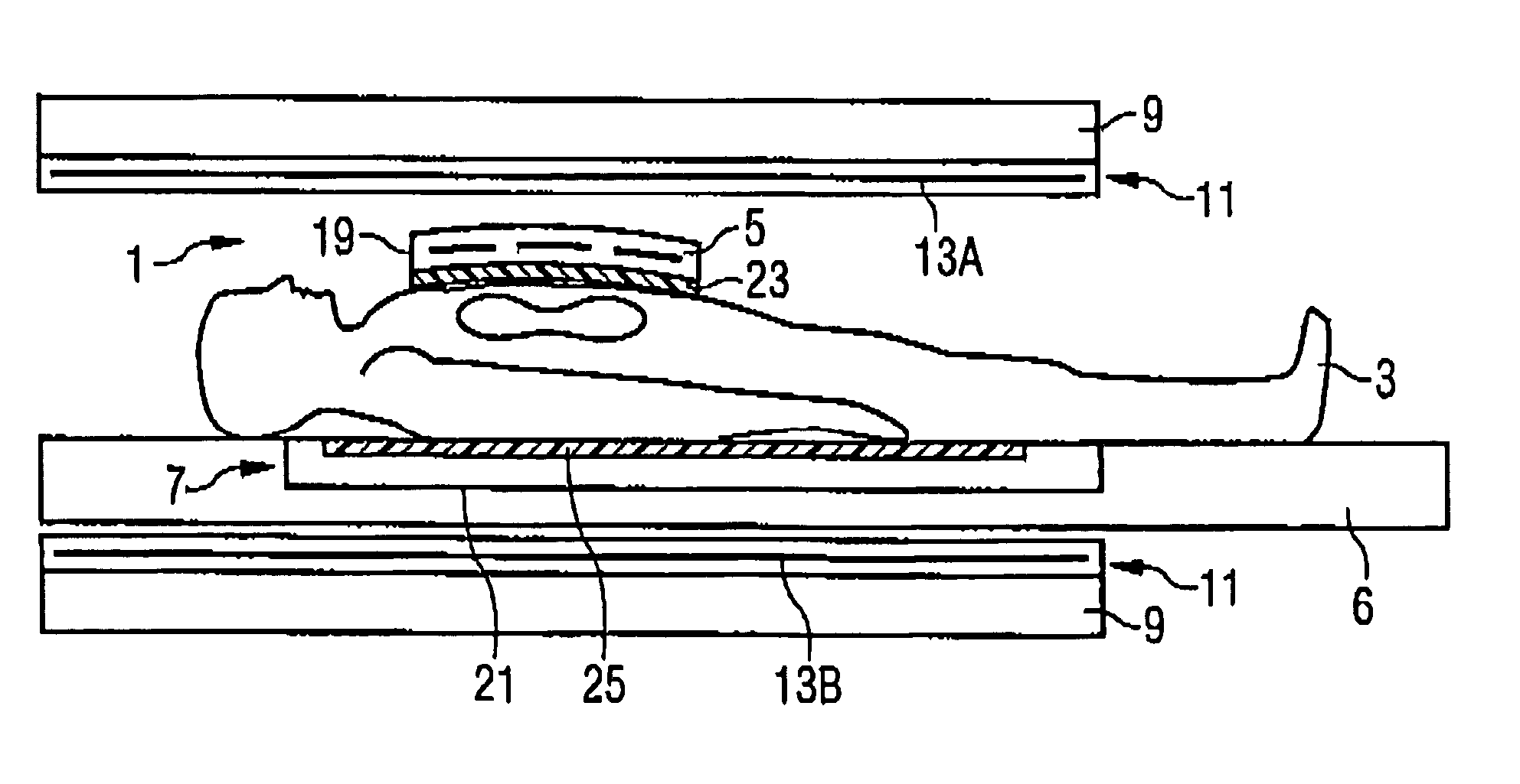
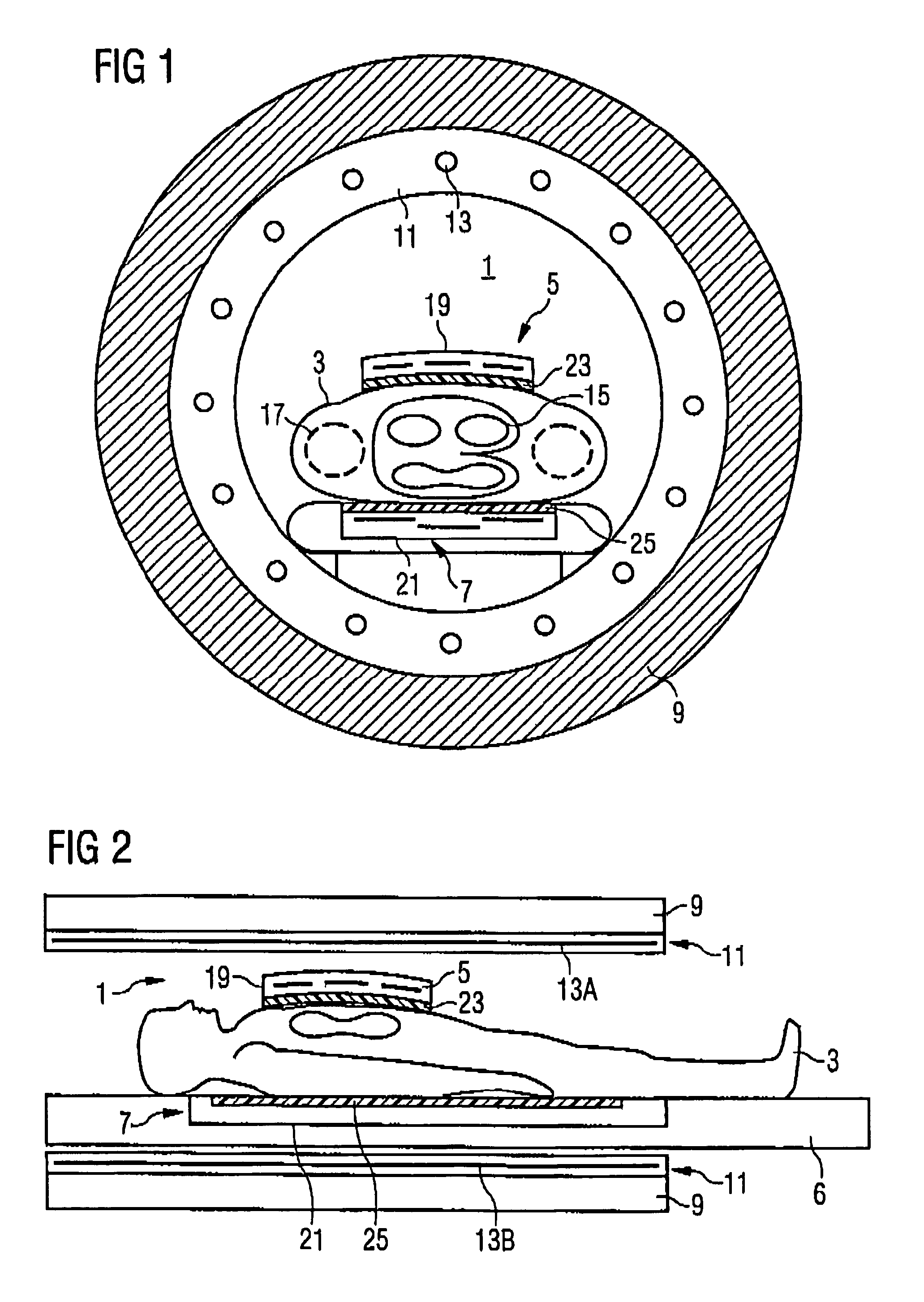
[0029]FIG. 1 shows a cross-section through an examination area 1 of a magnetic resonance device in which a patient 3 is being examined with a body and a spinal column unit 5,7.

[0030]With the aid of the base field magnet 9 the base magnetic field in the examination area 1 is generated. This is overlaid with the aid of a radio-frequency field generated by a whole-body antenna 11 within the body of the patient 3 it is desired to create as homogeneous a B1 field as possible. Residual inhomogeneities of the B1 field are sketched schematically in the body of patient 3. The solid lines 15 correspond to areas with reduced B1 field strength, the dashed lines 17 schematically sketch areas with increased B1 field strength. The inhomogeneities are essentially generated by inductively-created eddy currents in the patient 3. These flow in the heart area and in the area of the back musculature.

[0031]Magnetic resonance signals of the torso the of the patient 3 are received with local coil units, fo...


PUM


Abstract

A local coil unit for a magnetic resonance apparatus, which radiates a radio-frequency field into an examination subject, has a housing and at least a part of the housing is formed of an insulating dielectric material that passively compensates for an inhomogeneity in the high-frequency field in the subject. The material has a relative dielectric value εr of greater than 50, preferably greater than 100, and a dielectric loss factor tan δ of less than 2.5×10⁻², preferably less than 1×10⁻³. In the dielectric material displacement currents are generated which create an additional magnetic field that compensates for the minima in the B1 field as a result of the eddy currents arising in the patient due to the radio-frequency radiation.

Description

BACKGROUND OF THE INVENTION[0001]1. Field of the Invention[0002]The present invention relates to a local coil unit for a magnet resonance apparatus that radiates a radio-frequency field into an examination subject.[0003]2. Description of the Prior Art[0004]Magnetic resonance tomography has become a widely used technique for obtaining images of the inside of a body of a living subject under examination. To obtain an image using this technique the body or the part of the body to be investigated must initially be subjected to a static base magnetic field that is as homogeneous as possible (generally referred to as a B0 field) which is generated by a basic field magnet of the magnetic resonance device (MR device). During the data acquisition recording this basic magnetic field is overlaid with rapidly switched gradient fields for spatial coding, which are generated by gradient coils.[0005]Radio-frequency antennas are used to radiate radio-frequency pulses of a defined field strength int...

Claims


Application Information

Patent Timeline
Patent Type & Authority Patents(United States)
IPC IPC(8): G01V3/00G01R33/341
CPCG01R33/341
Inventor FEIWEIER, THORSTENLAZAR, RAZVANRENZ, WOLFGANGSCHON, LOTHAR
Owner SIEMENS HEALTHCARE GMBH
Why Eureka
Try Eureka