Projection optical system

a technology of projection optical system and projection lens, which is applied in the field of projection optical system, can solve the problems of difficult to achieve a wider angle, cannot be done without lengthening the focal length of the refractive lens group, and the lopsided positive direction of the projection sum, so as to achieve good optical performance, large screen, and advantageous in terms of mass production and cost

Active Publication Date: 2007-07-03
KONICA MINOLTA OPTO
View PDF9 Cites 25 Cited by
  • Summary
  • Abstract
  • Description
  • Claims
  • Application Information

AI Technical Summary

Benefits of technology

[0017]In view of the conventionally experienced inconveniences discussed above, it is an object of the present invention to provide a projection optical system that offers good optical performance, that is advantageous in terms of mass production and costs, that is slim and offers a large screen, and that is composed of lightweight and compact optical components.
[0024]According to the present invention, with a unique construction provided with a refractive lens group combined with a first and a second reflective optical elements having a positive and a negative optical power respectively, it is possible to realize a projection optical system that offers good optical performance, that is advantageous in terms of mass production and costs, that is slim and offers a large screen, and that is composed of lightweight and compact optical components.

Problems solved by technology

However, increasing the absolute value of the optical power of the negative mirror causes the Petzval sum to become lopsided in the positive direction.
This, however, cannot be done without lengthening the focal length of the refractive lens group, and thus brings an effect contrary to a wider angle.
Moreover, in a telecentric system, it is essential to dispose in the optical path a lens element having a strong positive optical power (causing the Petzval sum to be shifted in the positive direction) on the primary image surface side of the refractive lens group, and this makes it difficult to achieve a wider angle.
Doing any of these eventually makes the projection apparatus larger and increases costs.
However, as described above, the use of larger reflective optical elements and of a wider-angle refractive lens group makes it extremely difficult to lay out the optical path inside the rear projection apparatus, and thus makes it impossible to achieve a wider angle.
This increases the optical path length through the projection optical system, and is thus unsuitable for aiming at a wider angle or making the projection apparatus slim.
Such a shape, however, cannot be produced by turning, and its production and evaluation require sophisticated technologies as compared with a rotation-symmetric shape.
This may lead to higher costs.
The Petzval sum, if shifted in the positive direction by a negative mirror, can be shifted back in the negative direction with a positive mirror, but those are not achieved because of the other part of the construction and the inevitable restrictions.
This makes the optical path length greater and requires larger optical elements, and is thus unsuitable for aiming at a wider angle and further compactness.
Thus, this construction hardly differs from a coaxial optical system whose optical path is bent a plurality of times simply with flat reflective surfaces, and is thus unsuitable for aiming at a wider angle and further slimness.
Moreover, the inclination of the first mirror with respect to the screen shortens the optical path length at the top end of the screen, making the construction unsuitable for aiming at a wider angle by increasing the degree of eccentricity or of shifting.
This makes it difficult to correct for aberrations, and is thus unsuitable for aiming at higher performance.
Moreover, as increasingly wider angles are aimed at, the magnification of the projection optical system increases, and the second and third mirrors become larger as measured on the YZ plane (see FIG. 2 of the Patent Publication 3), making them difficult to produce and increasing costs.
Thus, this construction is unsuitable for aiming at a wider angle, further slimness, and lower cost.

Method used


Image

  • Projection optical system
  • Projection optical system
  • Projection optical system

Examples


examples

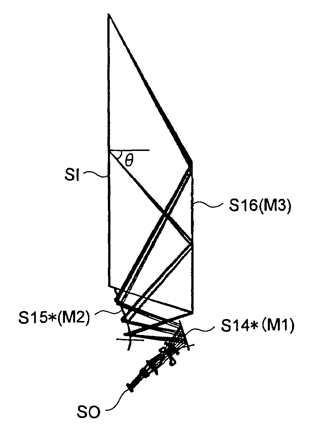
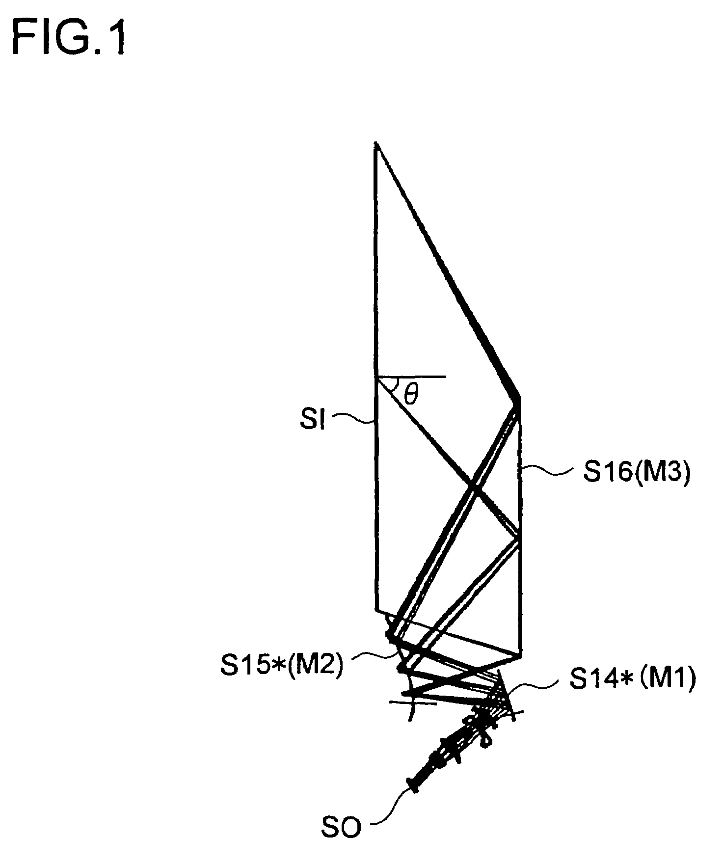
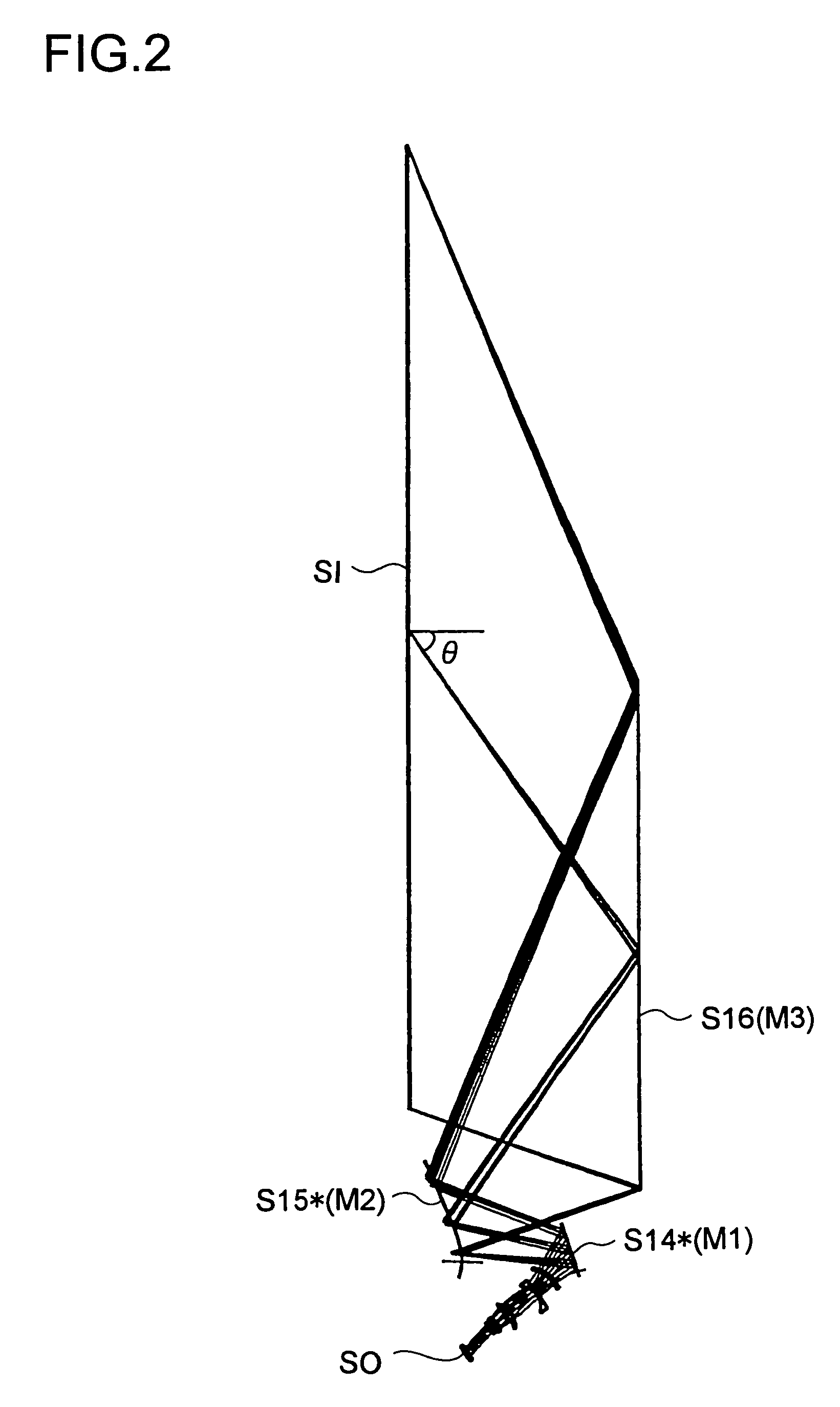
[0090]Hereinafter, practical examples of projection optical systems embodying the present invention will be presented with reference to their construction data and other data. Examples 1 to 4 presented below are numerical examples corresponding to the first to fourth embodiments described above, and the optical construction diagrams (FIGS. 1 to 8) showing the embodiments also show the optical arrangement, projection optical path, and other features of the corresponding examples.

[0091]Tables 1 to 4, Tables 5 to 8, Tables 9 to 12, and Tables 13 to 16 show the optical construction of Examples 1 to 4, respectively. Of these tables, Tables 1 and 2, Tables 5 and 6, Tables 9 and 10, and Tables 13 and 14 show, in the form of construction data, the optical arrangement of the entire system, specifically from the primary image surface SO (corresponding to the object surface in enlargement projection) on the reduction side to the secondary image surface SI (corresponding to the image surface in...


PUM


Abstract

A projection optical system for performing enlargement projection from a primary image surface on the reduction side to a secondary image surface on the enlargement side has, from the primary image surface side, a lens optical system including two or more lens elements sharing a common rotation-symmetry axis and each having an optical power, a first reflective optical element having an optical power, and a second reflective optical element having a negative optical power. The projection optical system is non-telecentric toward the reduction side, and a prescribed condition is.

Description

[0001]This application is based on Japanese Patent Application No. 2004-119501 filed on Apr. 14, 2004, the contents of which are hereby incorporated by reference.BACKGROUND OF THE INVENTION[0002]1. Field of the Invention[0003]The present invention relates to a projection optical system, and more particularly to a projection optical system that incorporates reflective and refractive optical elements in an optical construction suitable for rear projection.[0004]2. Description of Related Art[0005]In a projection optical system for performing wide-angle enlargement projection from a primary image surface on the reduction side to a secondary image surface on the enlargement side, disposing in the optical path a negative mirror closer to the secondary image surface is effective in reducing chromatic aberration and distortion. Projection optical systems including a negative mirror for reducing chromatic and other aberrations are proposed, for example, in Patent Publications 1 to 3 listed b...

Claims


Application Information

Patent Timeline
Patent Type & Authority Patents(United States)
IPC IPC(8): G02B9/00G03B21/22G03B21/28G02B17/08G02B13/08
CPCG02B13/08G02B17/0832G02B17/0852
Inventor KUWA, TOMIEI
Owner KONICA MINOLTA OPTO
Why Eureka
Try Eureka