Broadcast and select all optical network

Inactive Publication Date: 2006-10-10
OPVISTA +2
View PDF22 Cites 34 Cited by
  • Summary
  • Abstract
  • Description
  • Claims
  • Application Information

AI Technical Summary

Benefits of technology

[0016]A further object of the present invention is to provide an all optical fiber ring network that eliminates the need for in-line amplifier gain saturation on the ring.
[0018]These and other objects of the present invention are achieved in an all optical network for optical signal traffic. A first ring is included that has at least one transmitter and one receiver. The first ring includes a plurality of network nodes. At least a first add / drop broadband coupler is coupled to the first ring. The broadband coupler includes an add port and a drop port to add and drop wavelengths to and or from the first ring, a pass-through direction and an add / drop direction. The first add / drop broadband coupler is configured to minimize a pass-through loss in the first ring and is positioned on the first ring.
[0022]The first add / drop broadband coupler is coupled to the first ring and is configured to minimize a pass-through loss in the first ring. The broadband coupler is positioned on the first ring and includes an add port and a drop port to add and drop wavelengths to and or from the first ring, a pass-through direction and an add / drop direction.
[0036]14. The of above item number 10, wherein an open 1×1 switch is maintained on the first ring to eliminate a fiber ring basing phenomenon in response to gain provided by an in-line amplifier coupled to the first ring.

Problems solved by technology

The problem with this approach is that not only the center wavelength of each laser must be locked precisely, but also the physical size of the U-DWDM array may be large.
However, the physical size and the cost of the narrowband optical filters still present a problem.
In FIG. 1A, however, we can see that there are two sidebands representing the same modulating signal, and consequently half of the available bandwidth is wasted.
However, the signal coming out of the MZI still contains the undesired optical carrier.

Method used


Image

  • Broadcast and select all optical network
  • Broadcast and select all optical network
  • Broadcast and select all optical network

Examples


Embodiment Construction

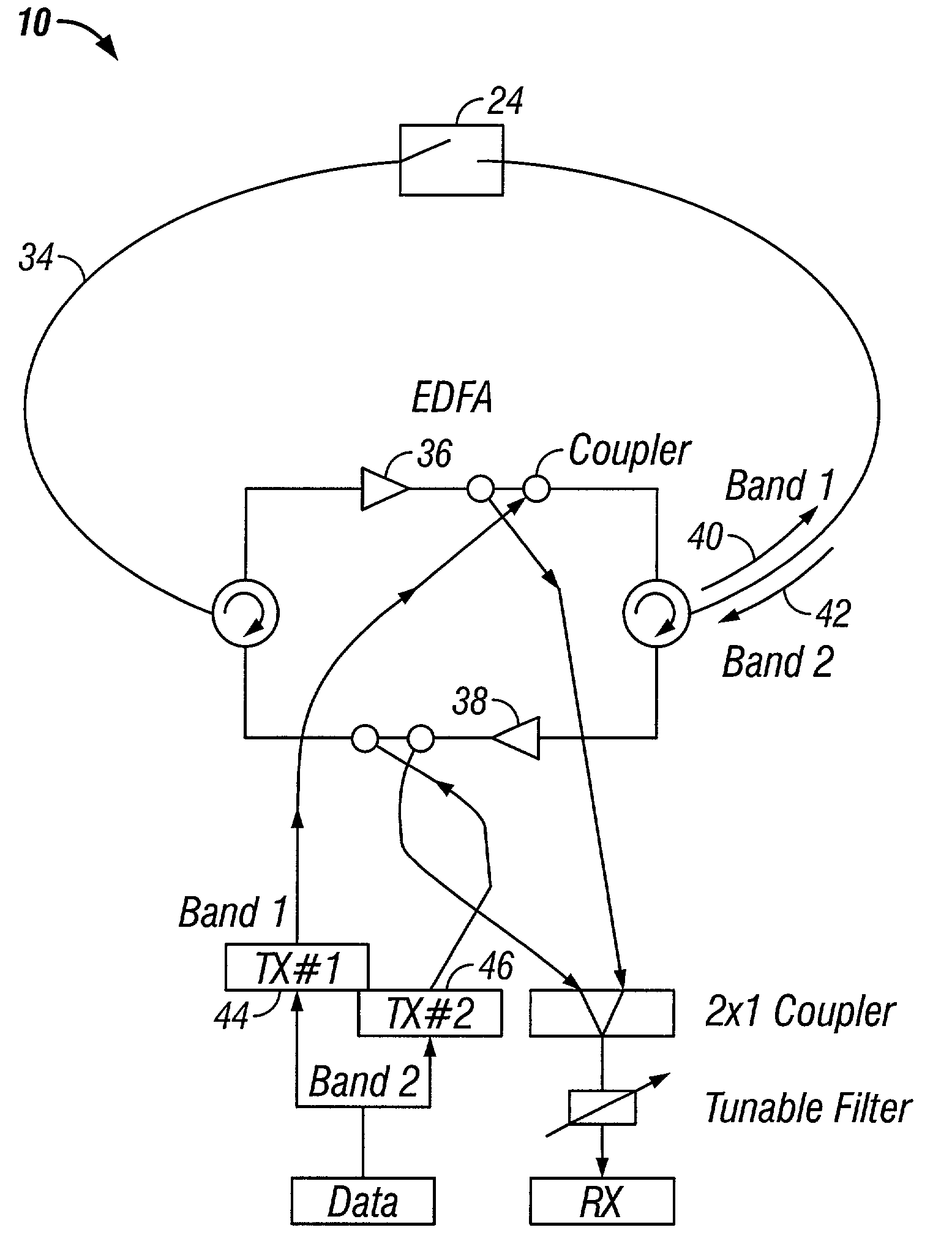
[0094]In one embodiment of the present invention, methods are provided for transmitting optical signal traffic. An all optical network is utilized with at least two rings that are geographically dispersed. Each ring has at least one transmitter and receiver. A sufficiently large enough number of wavelengths is shared in both rings to achieve the sharing without O-E-O conversions between the rings. Alternatively, the available wavelengths are separated into distinct ring bands. The optical signal traffic is shared throughout the entire optical network. Each ring is provided with its own distinct ring band of the optical signal traffic. All of the optical signal traffic is transmittable throughout the optical network. Each receiver is configured to receive only wavelengths in a ring band designated for its associated ring.

[0095]The present invention also provides all optical networks for optical signal traffic. In one embodiment the all optical network has at least first and second ri...


PUM


Abstract

An all optical network for optical signal traffic has at least a first ring with at least one transmitter and one receiver. The first ring includes a plurality of network nodes. At least a first add / drop broadband coupler is coupled to the first ring. The broadband coupler includes an add port and a drop port to add and drop wavelengths to and or from the first ring, a pass-through direction and an add / drop direction. The first add / drop broadband coupler is configured to minimize a pass-through loss in the first ring and is positioned on the first ring.

Description

CROSS-REFERENCE TO RELATED APPLICATIONS[0001]This application claims the benefit of U.S. application Ser. Nos. 60 / 229,784 filed Jun. 20, 2001, 60 / 301,564 filed Jun. 28, 2001, and 60 / 309,220 filed Jul. 31, 2001 and is also a continuation-in-part of U.S. Ser. No. 09 / 990,196 filed Nov. 21, 2001, now U.S. Pat. No. 6,896,184 and of Ser. No. 09 / 575,811 filed May 22, 2000, now U.S. Pat. No. 6,525,857 all of which applications are fully incorporated herein by reference.BACKGROUND OF THE INVENTION[0002]1. Field of the Invention[0003]The present invention relates generally to all optical networks, and more particularly to an all optical network that uses broadcast and select and minimizes pass-through losses between rings.[0004]2. Description of the Related Art[0005]In today's long-haul dense-wavelength-division-multiplexed (DWDM) optical networks, multiple regenerators have been replaced by optical amplifiers. However, when interconnecting two or more metro ring networks, or when interconnec...

Claims


Application Information

Patent Timeline
IPC IPC(8): H04B10/20H04B10/155H04B10/213H04J14/02H04Q11/00
CPCG02F1/0356H04B10/27H04B10/2755H04B10/503H04B10/505H04B10/506H04B10/5165H04B10/564H04J14/0204H04J14/0205H04J14/0206H04J14/0209H04J14/021H04J14/0212H04J14/0213H04J14/0217H04J14/0219H04J14/022H04J14/0227H04J14/0283H04J14/0294H04J14/0295H04Q11/0062H04J14/0241H04J14/0228G02F2001/212H04J14/0221H04J14/0286H04Q2011/0047H04Q2011/0092G02F1/212
Inventor WAY, WINSTON
Owner OPVISTA
Why Eureka
Try Eureka