Padlock

a technology of padlocks and locks, applied in the field of padlocks, can solve the problems of authorized security staff having great difficulties in opening luggage and checking personal items, and achieve the effect of strong structure and convenient operation

Inactive Publication Date: 2006-10-17
YU CHUN TE
View PDF12 Cites 28 Cited by
  • Summary
  • Abstract
  • Description
  • Claims
  • Application Information

AI Technical Summary

Benefits of technology

[0006]It is therefore an objective of the present invention to provide a padlock, which can be unlocked by either a combination locking device or a key locking device, and also to provide a padlock with strong structures and easy operating characteristics as well.

Problems solved by technology

Therefore, authorized security staff would have great difficulties in opening the luggage and checking the personal items due to safety concerns, if the luggage were locked by the padlocks with the single locking devices.

Method used


Image

  • Padlock
  • Padlock
  • Padlock

Examples


first embodiment

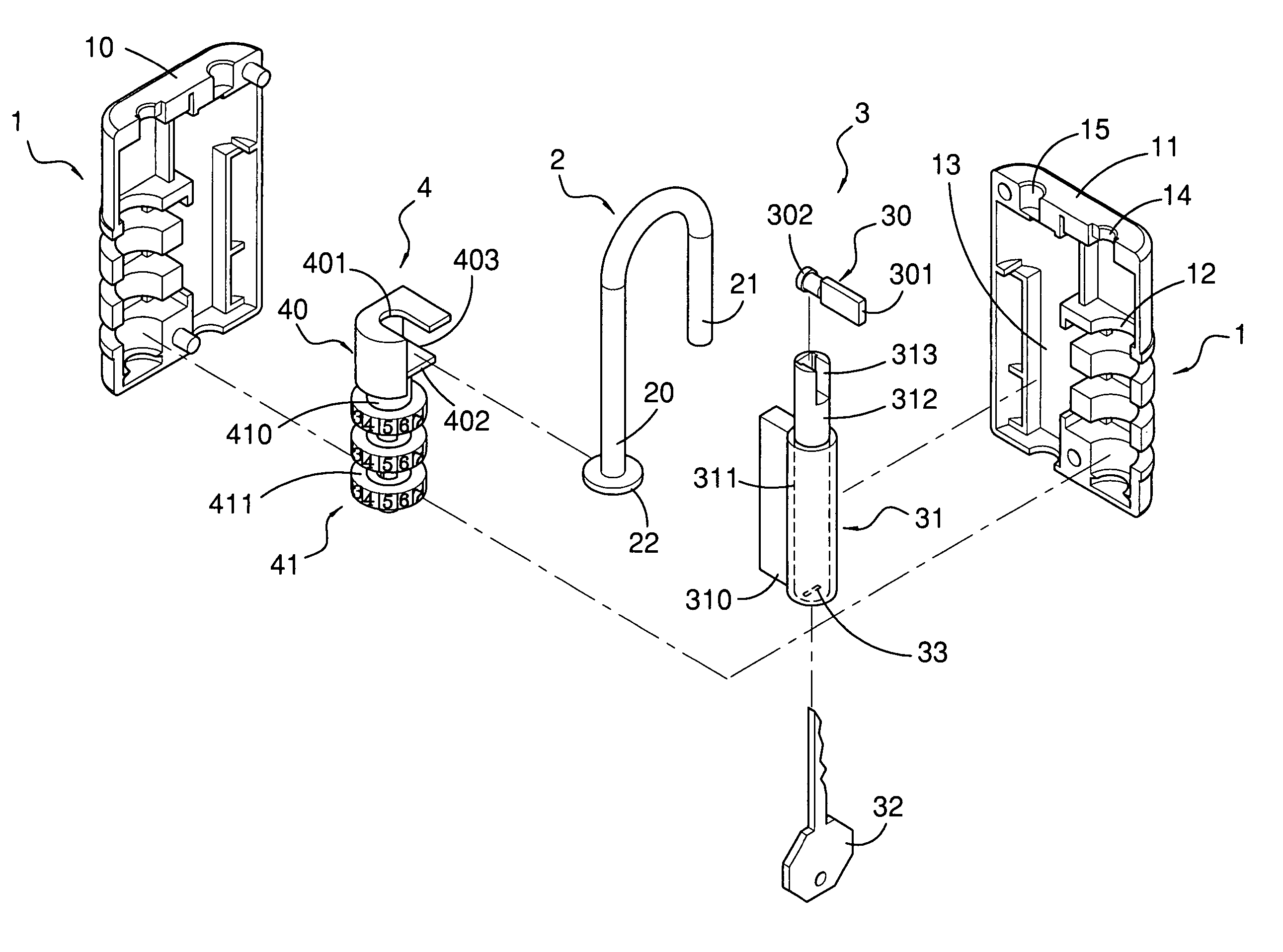
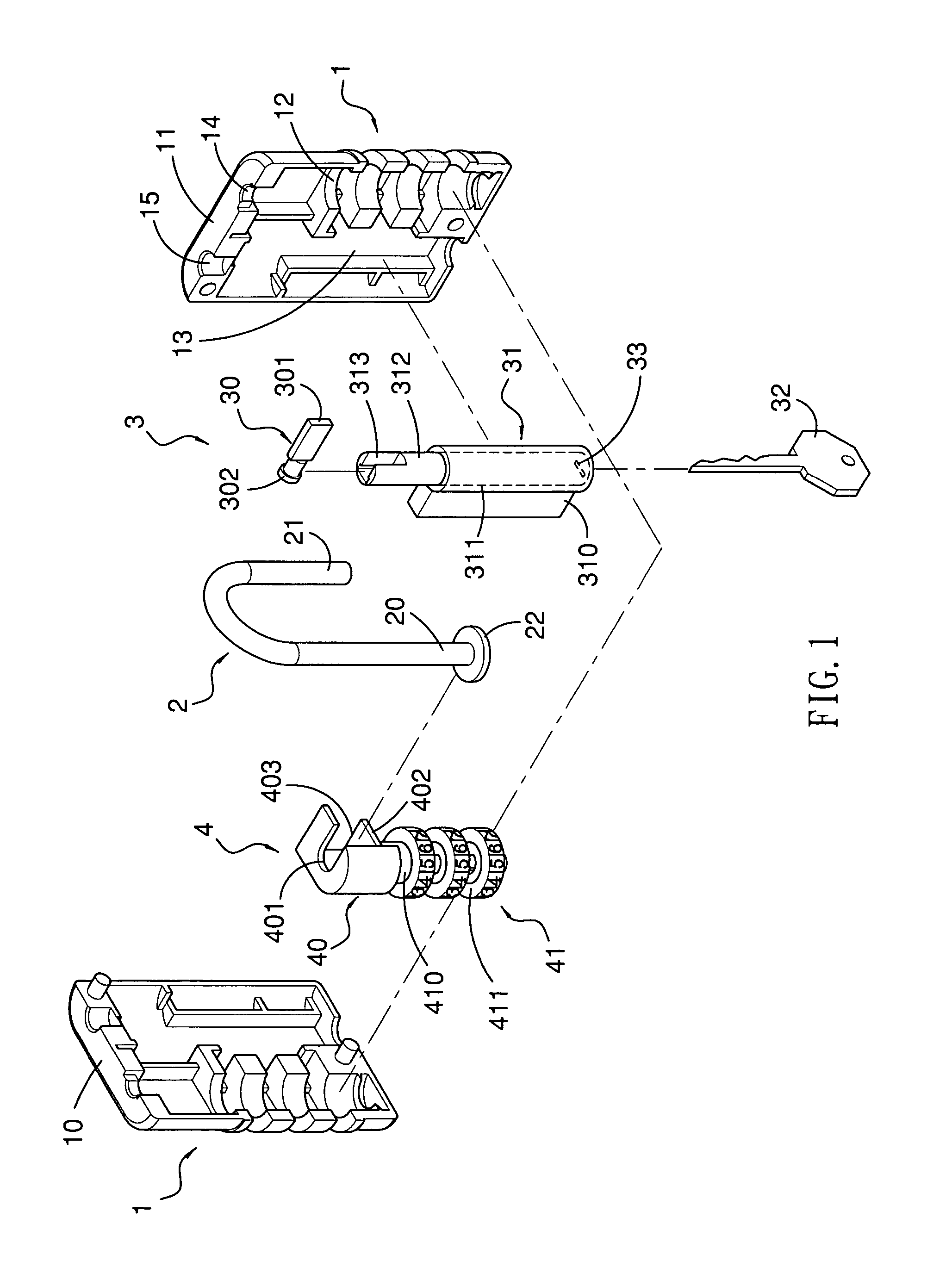
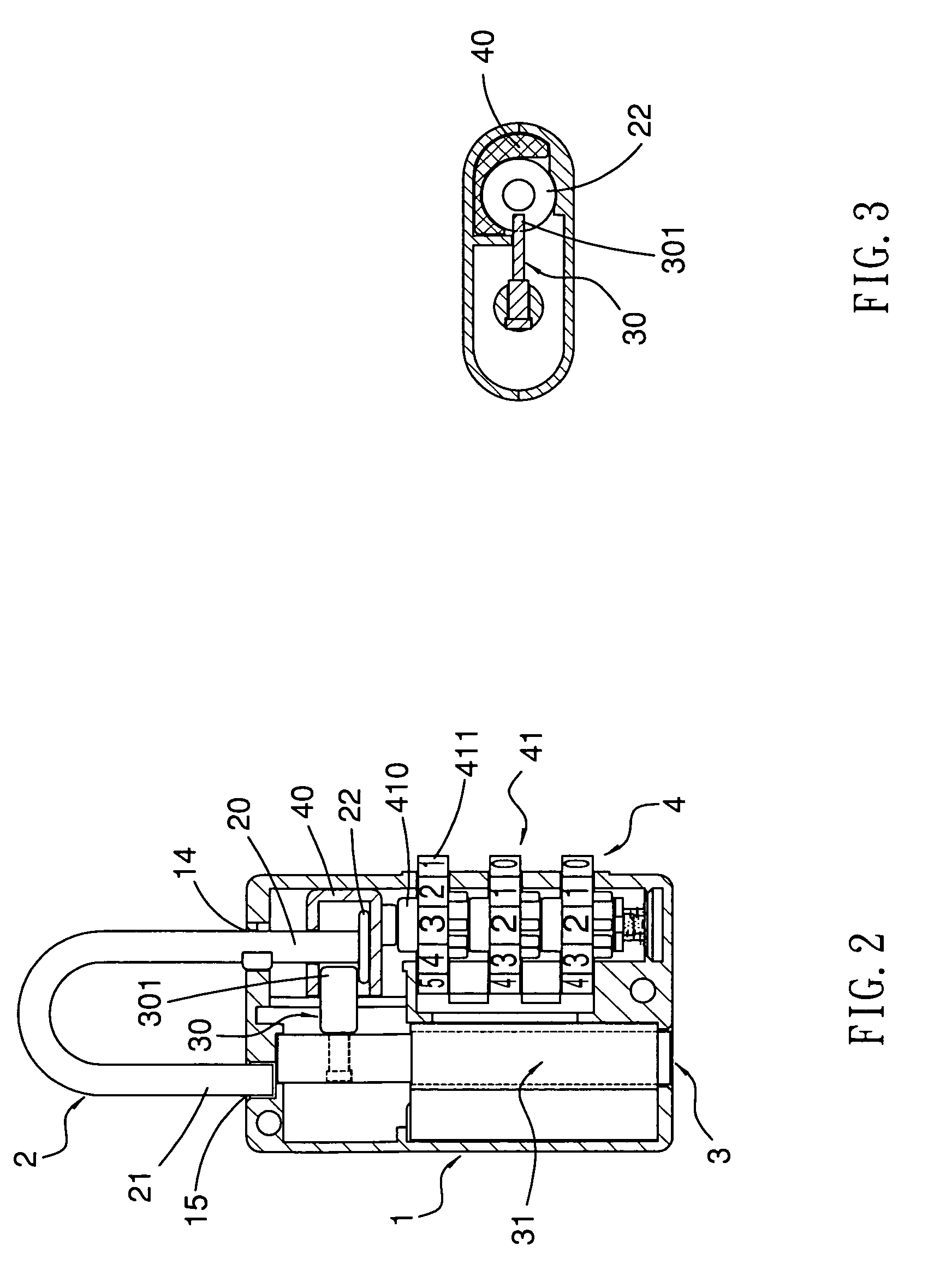
[0026]FIGS. 1–6 show a padlock as the present invention. In FIG. 1, the padlock comprises a lock body 1, a shackle 2, a key locking device 3 and a combination locking device 4. The lock body 1 includes a front cover 10 and a back cover 11 integrated with the front cover 10. Additionally, the lock body 1 has a first chamber 12 and a second chamber 13 formed therein; furthermore, the lock body 1 has a hole 14 intercommunicated with the first chamber 12, and a recess 15 formed thereon. The shackle 2 is movable relative to the lock body 1 between a locked position and an unlocked position. Moreover, the shackle 2 has a first end 20 movably installed within of the lock body 1 via the hole 14 and a second end 21 retainable within the recess 15 of the lock body 1 in the locked position. The first end 20 of the shackle 2 has a stop 22 at a distal end thereof.

[0027]In addition, the combination locking device 4 is installed within the first chamber 12 of the lock body 1 for controlling moveme...

second embodiment

[0034]FIGS. 8–9 show that the padlock of the second embodiment is locked. In the locked position, both the combination locking device 4a and the key locking device 3a are not operated, and the stop 22a of the first end 20a is blocked by the block end 301a of the block unit 30a so as to keep the first end 20a of the shackle 2a from moving. Furthermore, the stem 410a of the combination unit 41a and the frame 40a keep still because the unlocking numbers of the dials 411a are not dialed.

[0035]In FIG. 10, the padlock of the second embodiment is unlocked by operating the combination locking device 4a. Similarly to the first embodiment, the second end 21a of the shackle 2a is capable of removing from the recess 15a of the lock body 1a after the unlocking numbers of the dials 411a are dialed. When the unlocking numbers of the dials 411a are dialed, the stem 410a is moved upwardly together with the frame 40a and the first end 20a of the shackle 2a to a position where allows the second end 21...

third embodiment

[0038]FIGS. 13–14 show that the padlock of the third embodiment is locked. In the locked position, both the combination locking device 4b and the key locking device 3b are not operated, and the stop 22b of the first end 20b is blocked by the block end 301b of the block unit 30b so as to keep the first end 20b of the shackle 2b from moving. Meanwhile, the stop 22b of the first end 20b is retained in the lower bend 420 of the spring plate 42 to keep the stop 22b of the first end 20b in position.

[0039]In FIG. 15, the padlock of the third embodiment is unlocked by operating the combination locking device 4b. Similarly to the second embodiment, the second end 21b of the shackle 2b is capable of removing from the recess 15b of the lock body 1b after the unlocking numbers of the dials 411b are dialed. When the unlocking numbers of the dials 411b are dialed, the stem 410b is moved upwardly together with the frame 40b and the first end 20b of the shackle 2b to a position where allows the sec...


PUM


Abstract

A padlock comprises a lock body, a shackle, a combination locking device and a key locking device. The shackle is movable relative to the lock body between a locked position and an unlocked position. The combination and key locking devices are installed within the lock body respectively for controlling movements of the shackle. Additionally, the combination locking device has a frame for receiving a first end of the shackle and a combination unit connected to the frame, which is movable when the combination unit is unlock whereby a second end of the shackle is movable to the unlock position. Furthermore, the key locking device comprises a block unit for locking the first end of the shackle and a key unit connected to the block unit, which is movable when the key unit is unlocked by a key.

Description

CROSS REFERENCE TO RELATED APPLICATION[0001]This application is a continuation-in-part application of U.S. application Ser. No. 10 / 725,549 filed Dec. 3, 2003 now abandoned.TECHNICAL FIELD[0002]This invention relates generally to a padlock, in particular, to a padlock with dual locking devices.BACKGROUND OF THE INVENTION[0003]A conventional padlock with either a key locking device or a combination locking device is popular because the padlock with a single locking device is easy to use and such a padlock is provided for individual use only. Generally, travelers would apply different padlocks to lock their luggage so as to protect their personal items. Therefore, authorized security staff would have great difficulties in opening the luggage and checking the personal items due to safety concerns, if the luggage were locked by the padlocks with the single locking devices.[0004]Furthermore, another conventional padlock with dual locking devices, namely with a key and a combination lockin...

Claims


Application Information

Patent Timeline
Patent Type & Authority Patents(United States)
IPC IPC(8): E05B37/02
CPCE05B37/025Y10T70/415Y10T70/424Y10T70/463
Inventor YU, CHUN TE
Owner YU CHUN TE
Why Eureka
Try Eureka