

Electrical connector with interference collar
a technology of interference collar and electrical connector, which is applied in the direction of coupling contact members, coupling device connections, contact members penetrating/cutting insulation/cable strands, etc., to achieve the effect of easy manufacture, less cost and easy production
- Summary
- Abstract
- Description
- Claims
- Application Information
AI Technical Summary
Benefits of technology
Problems solved by technology
Method used
Image

Examples
Embodiment Construction
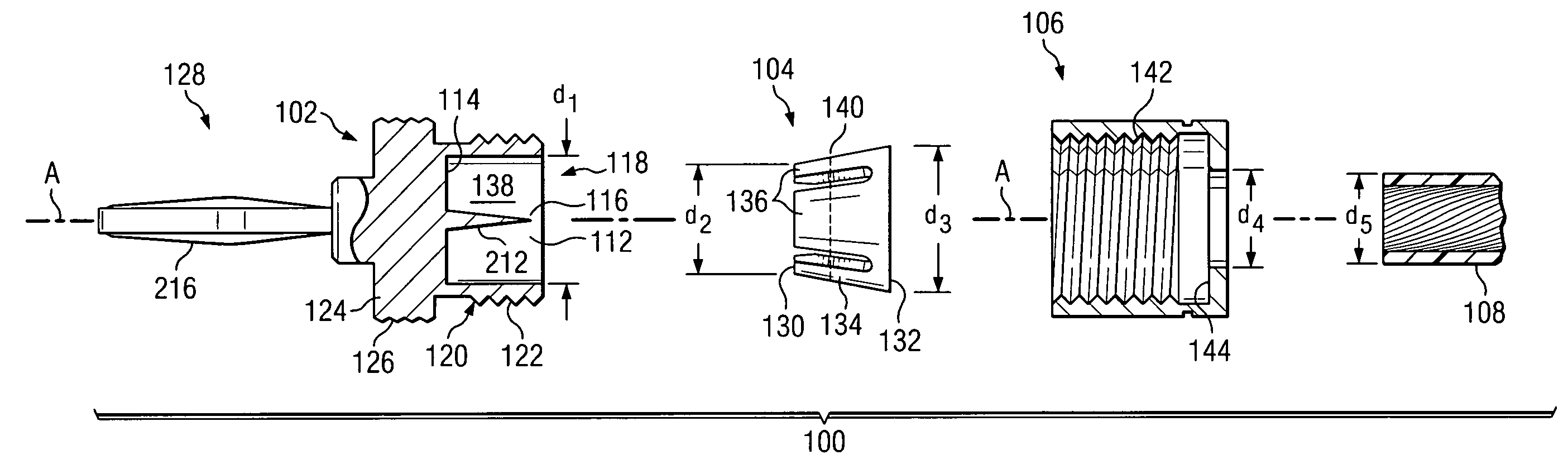
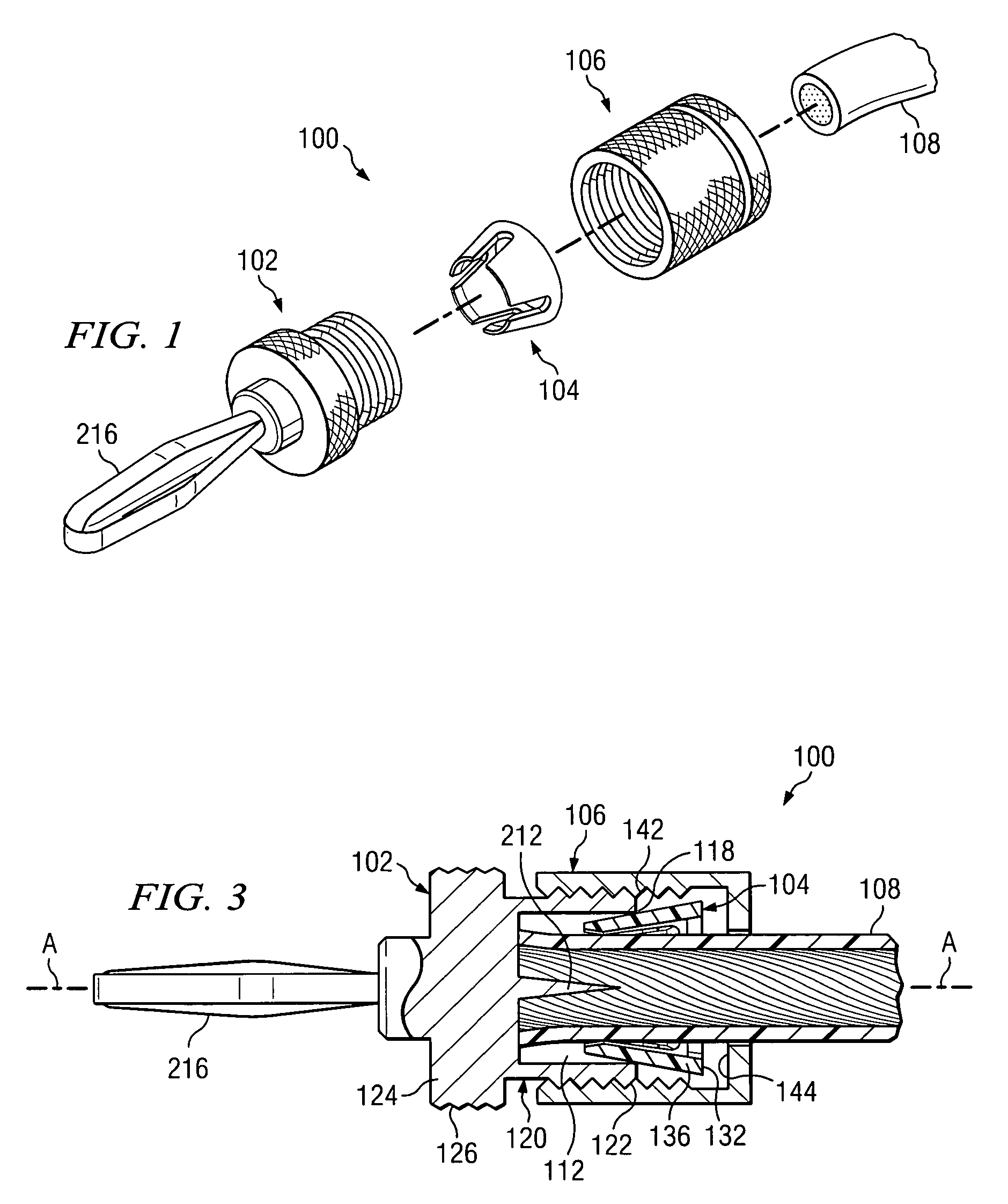
[0015]Referring first to FIG. 1, the present invention provides an electrical connector 100 which has, as its principal components, a housing 102, a collar 104 and a cap 106. The connector 100 is particularly useful in connecting a multistranded insulated conductor 108, of the type which is prevalent in the transmission of power (such as battery cables) and communications signals (such as speaker wires), although the invention can be used to connect to conductors of other types. As will be described in more detail below, the cap 106 and collar 104 are threaded onto the conductor 108, the conductor 108 is inserted into a bore of the housing 102 preferably to be impaled on a prong disposed therein, the collar 104 is wedged into the bore opening to clamp the conductor 108 in place, and the cap is attached as by threading to the collar 102 to hold the collar 104 and conductor 108 in place.
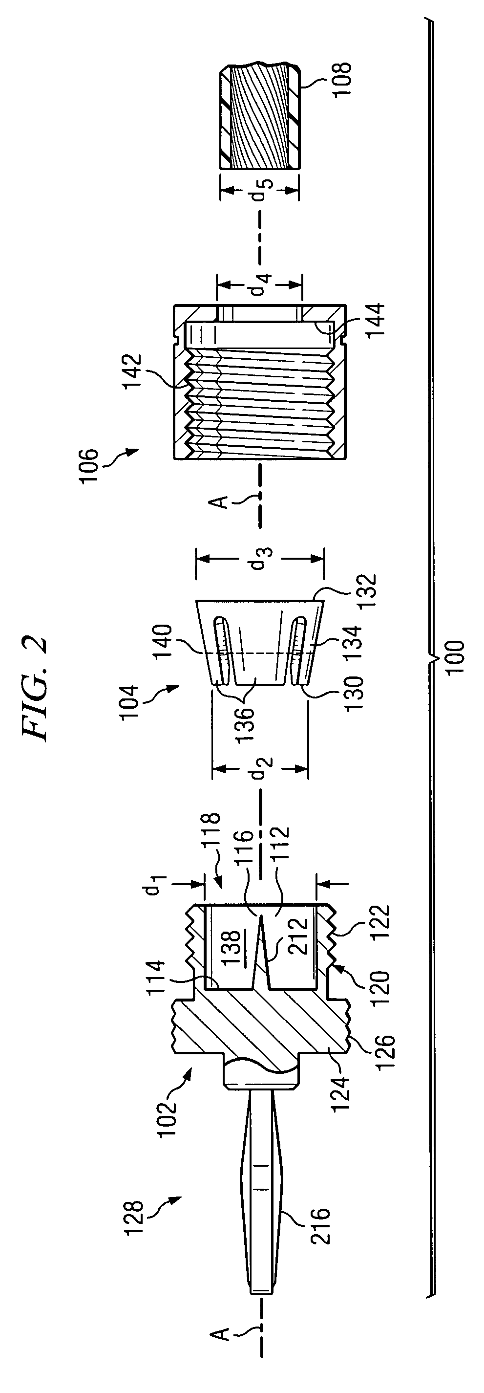
[0016]As seen in FIG. 2, the housing 102 has a preferably cylindrical bore 112 that is disposed aro...
PUM
 Abstract
Description
Claims
Application Information