Positioning structure in a golf club head

a golf club head and positioning structure technology, applied in the field of positioning structure, can solve the problems of time-consuming and labor-intensive, and achieve the effect of improving the positioning structur

Inactive Publication Date: 2006-10-17
ADVANCED INT MILITIECH
View PDF6 Cites 94 Cited by
  • Summary
  • Abstract
  • Description
  • Claims
  • Application Information

AI Technical Summary

Benefits of technology

[0007]The primary objective of the present invention is to provide an improved positioning structure b

Problems solved by technology

Furthermore, the solder fillet (42) formed on the joint between the flange (411) of the striking face (41) and the peripheral edge of t

Method used


Image

  • Positioning structure in a golf club head
  • Positioning structure in a golf club head
  • Positioning structure in a golf club head

Examples


Embodiment Construction

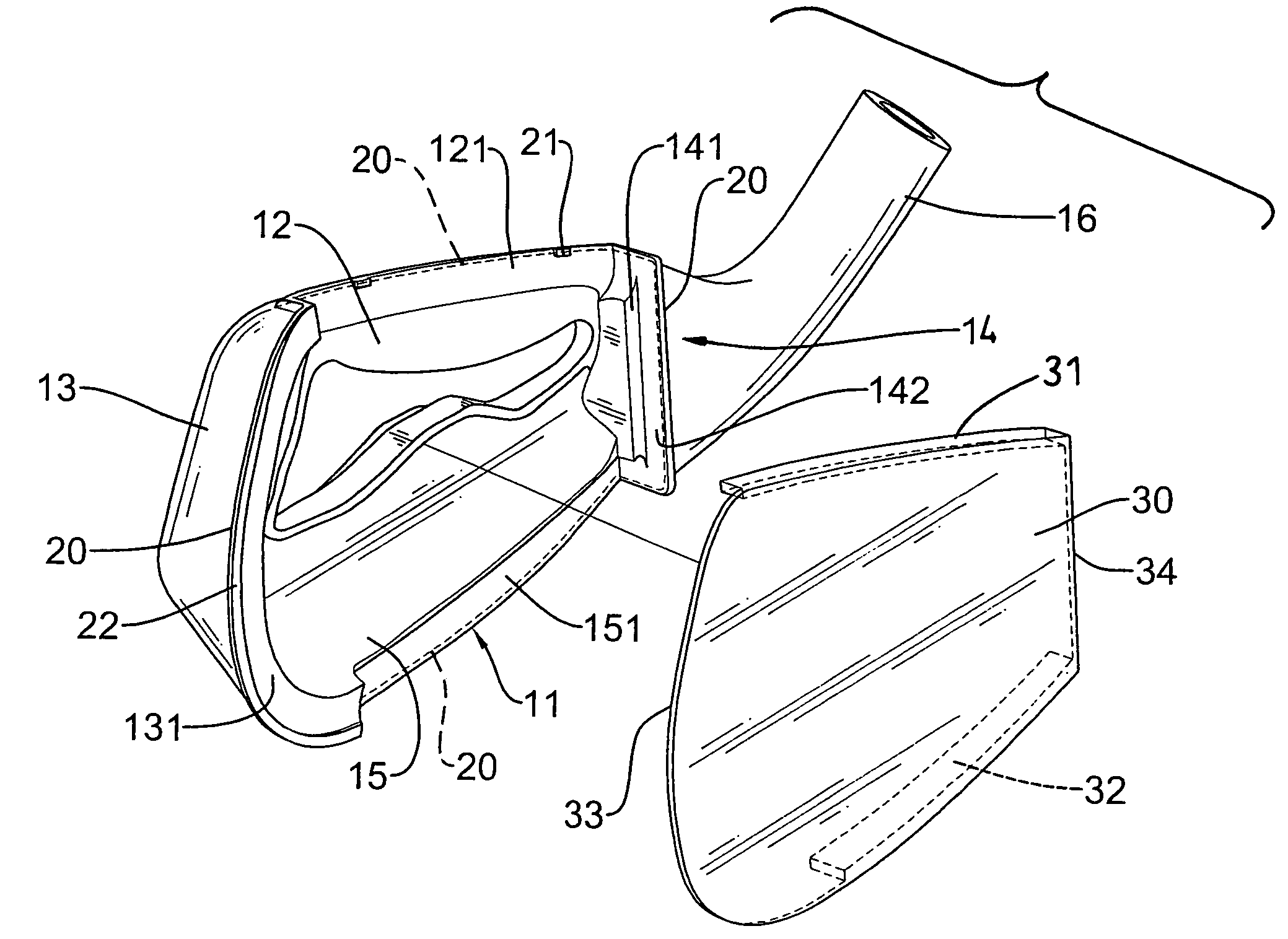
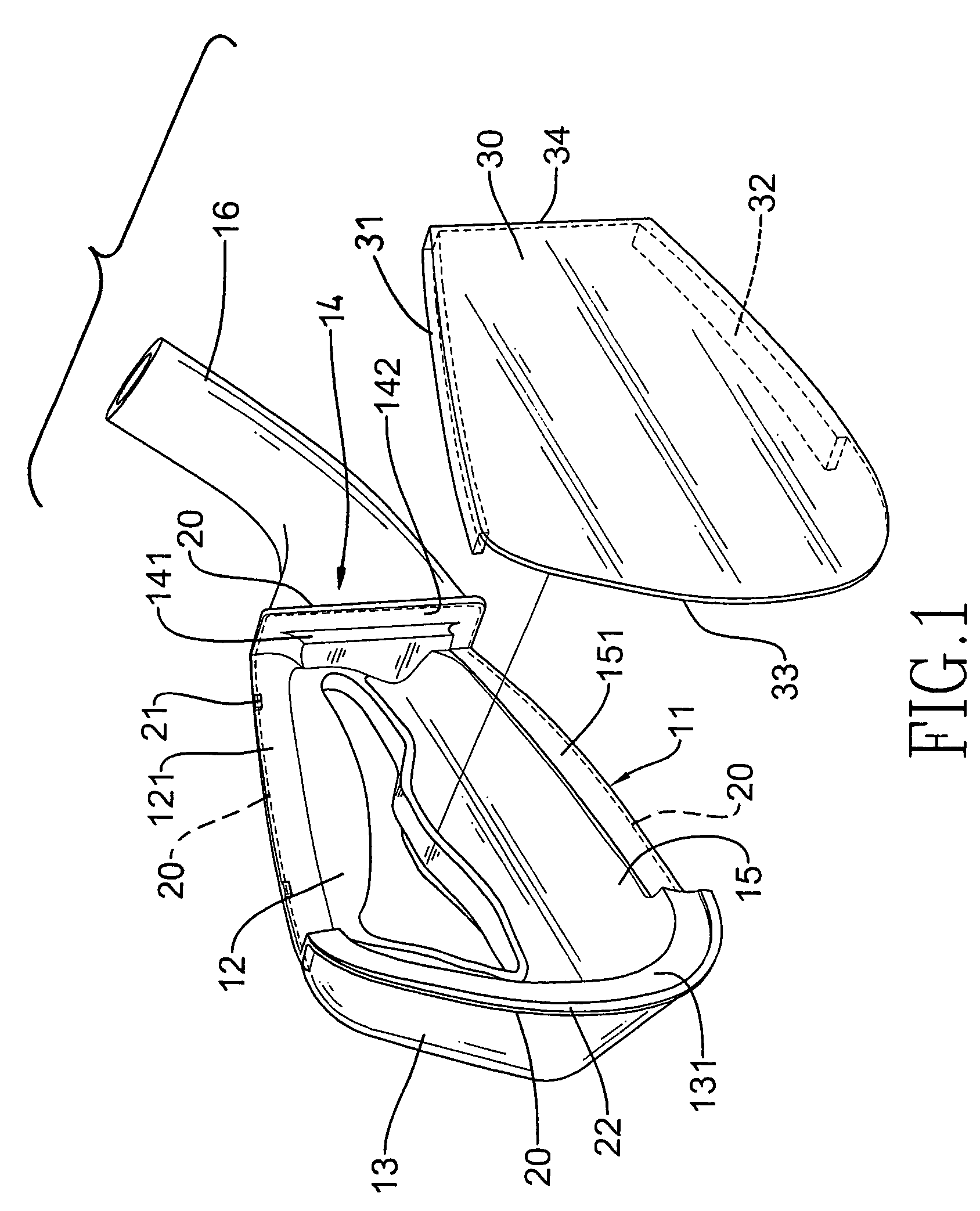
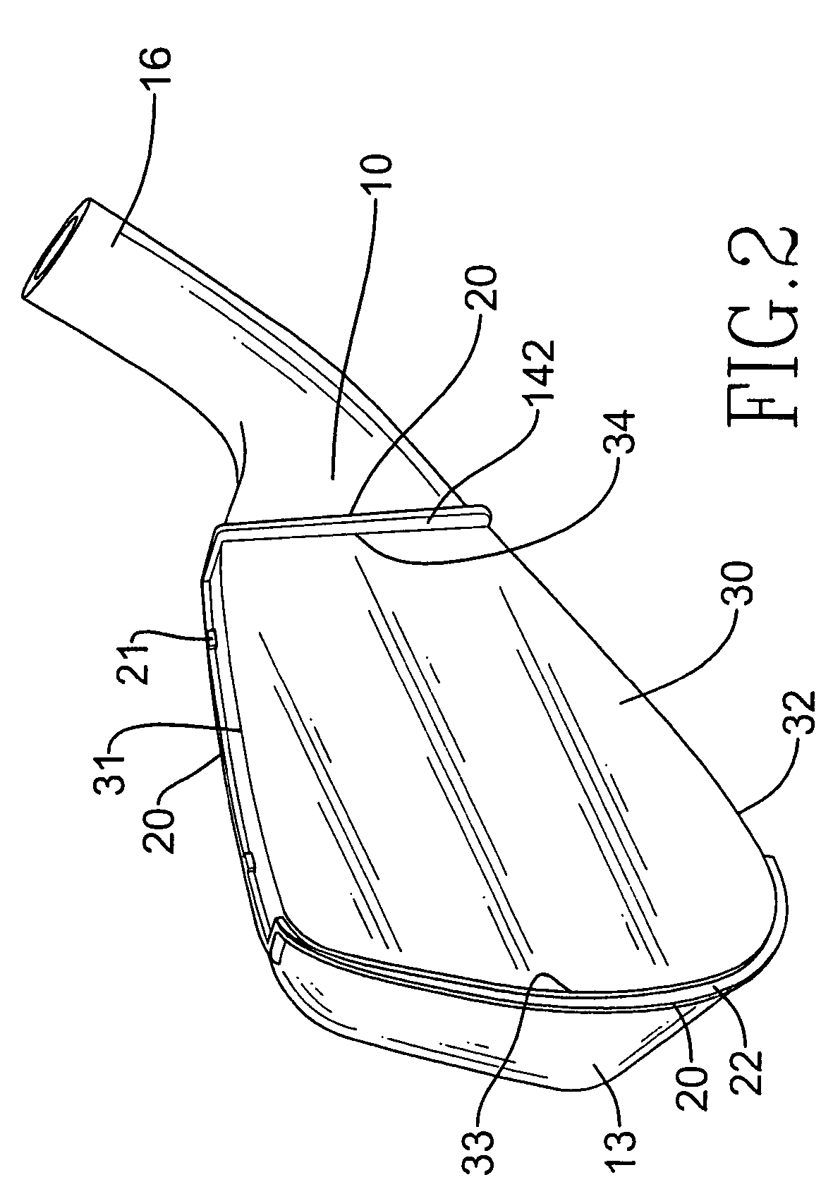
[0017]With reference to FIG. 1, the golf club head in accordance with the present invention has a head body (10) and a striking face (30).

[0018]The head body (10) has a recessed area (11) defined in a central area of the head body (10), a rear plate (12), a first side plate (13), a second side plate (14) opposite to the first side plate (13), a bottom plate (15) and a neck (16) The rear plate (12) forms a bottom face defining the recessed area (11) and has a rear plate abutting face (121) at a top edge of the rear plate (12) The first side plate (13) is arcuate and integrally formed with the rear plate (12) and has a first side plate abutting face (131) at a free edge of the first side plate (13) The second side plate (14) is integrally formed with the rear plate (12) and has a second side plate abutting face (141) formed adjacent to a free edge of the second side plate (14) and a flat face (142) sandwiched between the free edge of the second side plate (14) and the second side plat...


PUM


Abstract

A golf club head includes a head body having a recessed area defined in a central area of the head body and abutting faces formed along a periphery defining the recessed area. A soldering seam is formed on an outer periphery defining the recessed area and at least one positioning block is formed on one of the abutting faces and has a bottom face flush with a top face of the recessed area. A striking face is abutted to the abutting faces and the bottom face of the positioning block to allow the soldering seam to securely combine the head body and the striking face.

Description

BACKGROUND OF THE INVENTION[0001]1. Field of the Invention[0002]The present invention relates to a positioning structure, and more particularly to positioning structure in a golf club head to facilitate the mating between the head body and the striking face so that the welding process is shortened.[0003]2. Description of Related Art[0004]A golf club head usually is composed of different parts welded together. With reference to FIG. 7, a conventional the conventional golf club head is composed of a head body (40) and a striking face (41). The striking face (41) has a flange (411) formed on a peripheral edge of the striking face (41) to abut a peripheral edge of the head body (40). After the flange (411) of the striking face (41) is abutted the peripheral edge of the head body (40), a solder fillet (42) is formed between a joint between the flange (411) of the striking face (41) and the peripheral edge of the head body (40).[0005]During the mating process between the head body (40) an...

Claims


Application Information

Patent Timeline
IPC IPC(8): A63B53/04A63B102/32
CPCA63B53/047A63B53/0475A63B2053/0416A63B53/0416
Inventor CHENG, BERNARDCHEN, ANITAAKINORI, SASAMOTOLIN, MAY
Owner ADVANCED INT MILITIECH
Why Eureka
Try Eureka