8-inch vacuum booster assembly with floating diaphragm structure

A vacuum booster, floating technology, applied in the direction of brakes, brake transmissions, transportation and packaging, etc., can solve the problems of vacuum booster failure, achieve good positioning, improve product reliability, and simple assembly

Pending Publication Date: 2019-01-11
JILIN DONGGUANG AOWEI AUTOMOBILE BRAKE SYST
View PDF0 Cites 0 Cited by
  • Summary
  • Abstract
  • Description
  • Claims
  • Application Information

AI Technical Summary

Problems solved by technology

[0005] The invention provides an 8-inch vacuum booster assembly with a floating diaphragm structure to solve the problem of failure of the vacuum booster due to improper assembly of the diaphragm and the valve body

Method used


Image

  • 8-inch vacuum booster assembly with floating diaphragm structure
  • 8-inch vacuum booster assembly with floating diaphragm structure
  • 8-inch vacuum booster assembly with floating diaphragm structure

Examples


Embodiment Construction

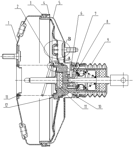
[0014] The front shell part 1 is riveted with the rear shell part 5, the diaphragm 3 is installed between the front shell part 1 and the rear shell part 5, and the rear shell air seal 7 is interference fit with the rear shell part 5 to form a sealed shell , the rear shell air seal 5 is interference fit with the valve body 2, the booster disc 4 is riveted with the valve body 2, the control valve part 8 and the valve body 2 are clamped and assembled through the lock plate 6, the feedback disc 10, the retainer 12, the master cylinder push The rod 11 is fitted inside the valve body 2 , the return spring 13 is fitted on the retainer 12 , and the dust cover 9 is fitted on the rear housing part 5 .

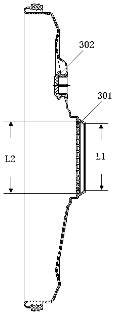
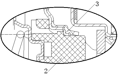
[0015] There is a floating sealing structure 301 and a clamping positioning structure 302 on the diaphragm 3, and the valve body 2 is connected to the diaphragm 3 through the floating sealing structure 301. The floating sealing structure 301 has a sealing ring one L1 and a sealing ring tw...


PUM


Abstract

The invention relates to an 8-inch vacuum booster assembly with a floating diaphragm structure, belonging to the technical field of automobile braking systems. The front housing part is riveted to therear housing part. A diaphragm is arranged between the front housing part and the rear housing part. The rear housing gas seal is interference-fitted with the rear housing part to form a sealed shell, and the rear housing gas seal is interference-fitted with the valve body. The booster disk is riveted with the valve body, and the control valve part and the valve body are clamped and assembled through a locking plate. The feedback disk, the retainer ring, and the master cylinder push rod are assembled in the valve body, and the return spring is assembled on the retainer ring, and the dust cover is assembled on the rear housing part. The 8-inch vacuum booster assembly with a floating diaphragm structure has the advantages of novel structure, improved product reliability, good positioning, simple assembly, small occupying space and easy processing.

Description

technical field [0001] The invention belongs to the technical field of automobile brake systems, in particular to a vacuum booster assembly. Background technique [0002] The existing conventional vacuum booster assembly used for automobile braking consists of: front housing, rear housing, rear housing bolts, rear housing air seal, control valve parts, lock plate, dust cover, adjustment fork, pressure block, Feedback plate, master cylinder push rod, retainer, return spring, valve body, diaphragm, booster plate and other main components. [0003] During the operation of the conventional vacuum booster assembly, the input force from the brake pedal drives the control valve part to cooperate with the valve body, and the vacuum booster assembly is divided into two chambers, the front chamber is the vacuum chamber, and the rear chamber is connected to the atmosphere through the diaphragm. , which is affected by atmospheric pressure to produce a boosting effect. [0004] However...

Claims


Application Information

Patent Timeline
IPC IPC(8): B60T13/52B60T13/569B60T13/567
CPCB60T13/52B60T13/567B60T13/569
Inventor 徐勇季宁张世强王维刘佳奇张玉海
Owner JILIN DONGGUANG AOWEI AUTOMOBILE BRAKE SYST
Why Eureka
Try Eureka