Polishing equipment for metal material machining and convenient positioning structure of polishing equipment

A metal material, positioning structure technology, applied in metal processing equipment, grinding/polishing equipment, grinding machine parts and other directions, can solve the friction of metal material grinding equipment, the surface of metal materials cannot be polished, and the damage of metal grinding equipment and other problems to achieve the effect of improving practicability, increasing stability and improving stability

Pending Publication Date: 2020-08-21
ZHENGZHOU RAILWAY VOCATIONAL & TECH COLLEGE
View PDF0 Cites 1 Cited by
  • Summary
  • Abstract
  • Description
  • Claims
  • Application Information

AI Technical Summary

Problems solved by technology

[0004] Aiming at the problems existing in the prior art, the present invention provides a grinding device for metal material processing and its convenient positioning structure, which has the advantage of conveniently fixing the metal material, and solves the problem of the metal material being damaged

Method used


Image

  • Polishing equipment for metal material machining and convenient positioning structure of polishing equipment
  • Polishing equipment for metal material machining and convenient positioning structure of polishing equipment
  • Polishing equipment for metal material machining and convenient positioning structure of polishing equipment

Examples


Embodiment Construction

[0031] In order to further understand the content, features and effects of the present invention, the following examples are given, and detailed descriptions are given below with reference to the accompanying drawings.

[0032] The structure of the present invention will be described in detail below in conjunction with the accompanying drawings.

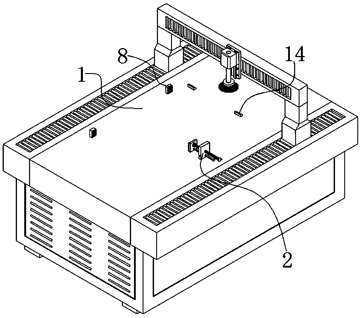
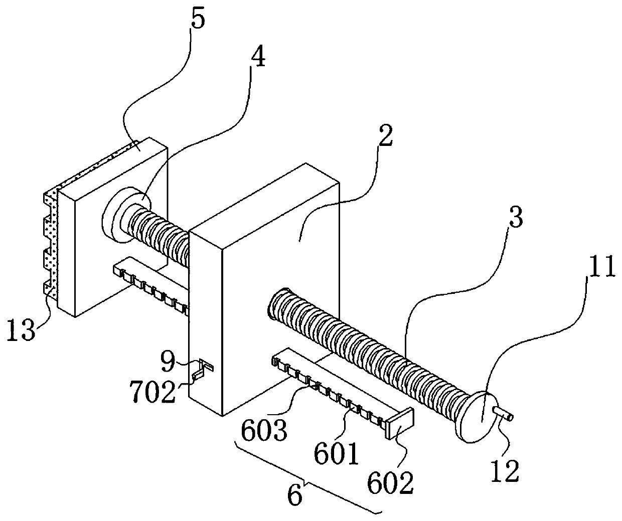
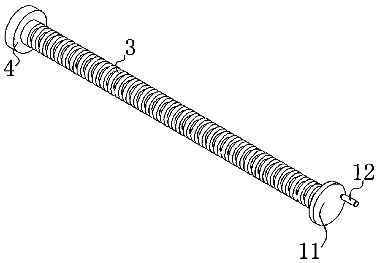
[0033] Such as Figure 1 to Figure 8 As shown, a kind of grinding equipment for metal material processing and its convenient positioning structure provided by the embodiment of the present invention includes a grinding device 1, the right side of the top of the grinding device 1 is fixedly connected with a first fixed plate 2, and the first fixed plate 2 The internal thread of the screw rod 3 is connected with the screw rod 3, the left side of the surface of the screw rod 3 is fixedly connected with the bearing 4, the left side of the bearing 4 is fixedly connected with the second fixed plate 5, and the bottom of the right side of th...


PUM


Abstract

The invention discloses polishing equipment for metal material machining and a convenient positioning structure of the polishing equipment. The polishing equipment for metal material machining and theconvenient positioning structure of the polishing equipment comprise a polishing device, wherein a first fixing plate is fixedly connected to the right side of the top of the polishing device. According to the polishing equipment for metal material machining and the convenient positioning structure of the polishing equipment, the polishing device, the first fixing plate, a screw rod, a bearing, asecond fixing plate, a limiting member, a first fixing rod, an anti-falling block, openings, a clamping member, a rotating disc, a second fixing rod, a clamping rod, first limiting blocks, an openinghole, a spring, a turntable, a rotating handle, a rubber pad and a second limiting block are matched to use, and thus the following problems when existing metal polishing equipment is used are solved: the surface of a metal material cannot be polished due to the fact that the metal material is prone to moving, and the metal material is deformed or the metal polishing equipment is damaged due to friction between the metal material and the metal polishing equipment; and the polishing equipment for metal material machining and the convenient positioning structure of the polishing equipment havethe advantage of being capable of fixing the metal material conveniently, and thus the practicability of the metal polishing equipment is improved.

Description

technical field [0001] The invention belongs to the technical field of metal grinding, and in particular relates to a grinding device for metal material processing and a convenient positioning structure thereof. Background technique [0002] Metal material refers to the collective name of metal elements or materials with metal properties mainly composed of metal elements, including pure metals, alloys, intermetallic compounds of metal materials and special metal materials. [0003] Metal material processing requires the use of grinding equipment. The existing problems in the prior art are: the position of the metal material is easy to move during the use of the metal grinding equipment, which will cause the surface of the metal material to not be polished and friction with the metal material grinding equipment, resulting in metal material The phenomenon of deformation or damage to the metal grinding equipment is inconvenient for users and reduces the practicability of the me...

Claims


Application Information

Patent Timeline
IPC IPC(8): B24B19/00B24B41/06B24B47/00B24B55/00
CPCB24B19/00B24B41/06B24B47/00B24B55/00
Inventor 王净丰吴甜甜楚亚杰焦文达房新荷邵长辉张家宁吉海洋孙东瑾
Owner ZHENGZHOU RAILWAY VOCATIONAL & TECH COLLEGE
Why Eureka
Try Eureka