Scanning method and apparatus

a scanning method and scanning technology, applied in the field of scanning methods and apparatuses, can solve the problems of large variation in scanning speed, singularity at the centre of the field, and feasible resonance operation

Inactive Publication Date: 2006-10-17
OPTISCAN
View PDF7 Cites 32 Cited by
  • Summary
  • Abstract
  • Description
  • Claims
  • Application Information

AI Technical Summary

Problems solved by technology

However, as demand increases for ever more compact scanners there is a need to develop a combined XY scanner of shortest possible length.
The problem is that for practical forces only resonant operation is feasible.
However, the modulation of the radius of the scanning circle or ellipse results in a large variation in scanning speed, and a singularity at the centre of the field.
This scan pattern is very different from a raster scan, so the resulting circular pattern requires image processing, creating interface problems with standard systems.
Hence most of the central area cannot be accessed.

Method used


Image

  • Scanning method and apparatus
  • Scanning method and apparatus
  • Scanning method and apparatus

Examples


Embodiment Construction

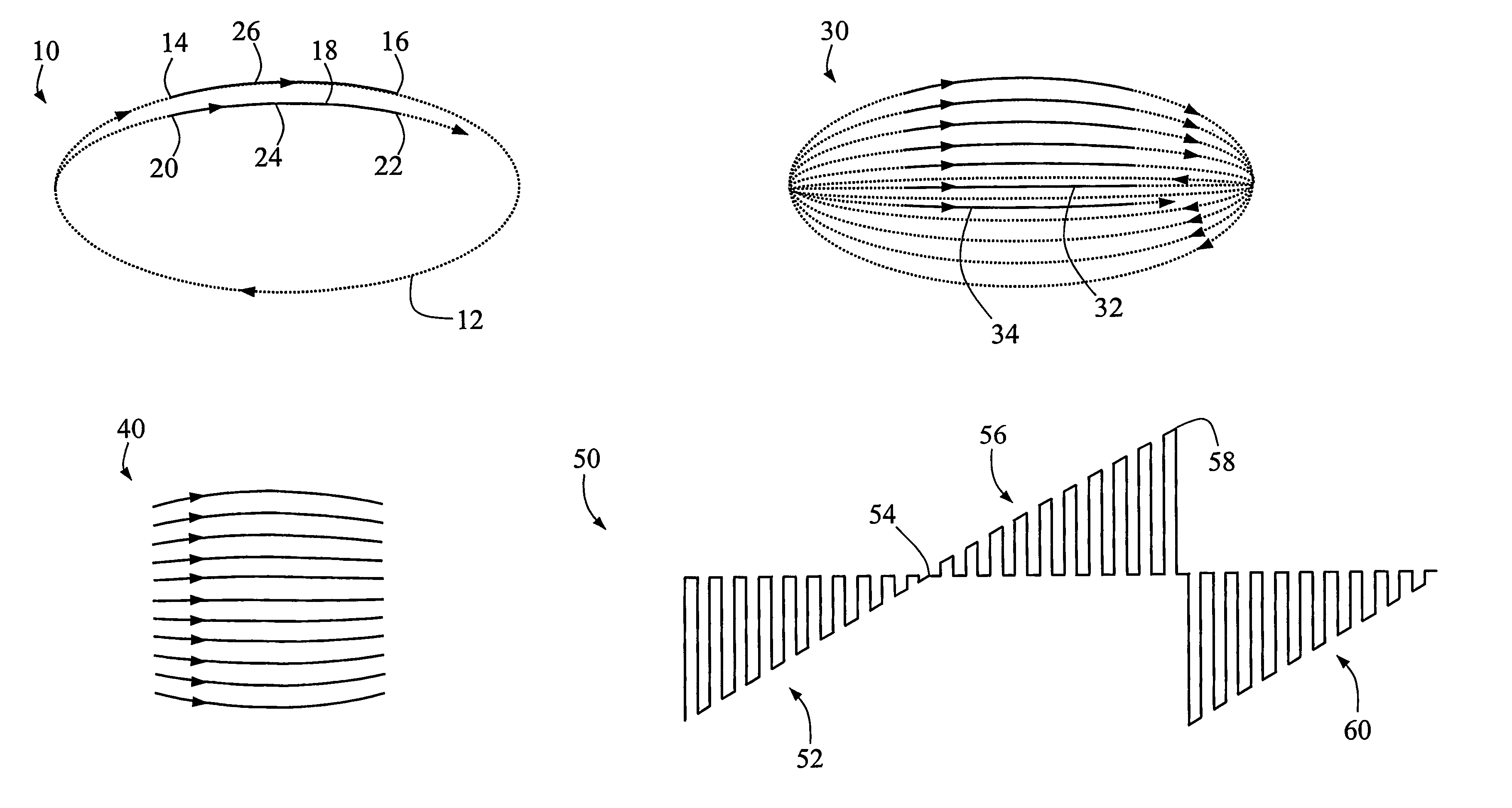
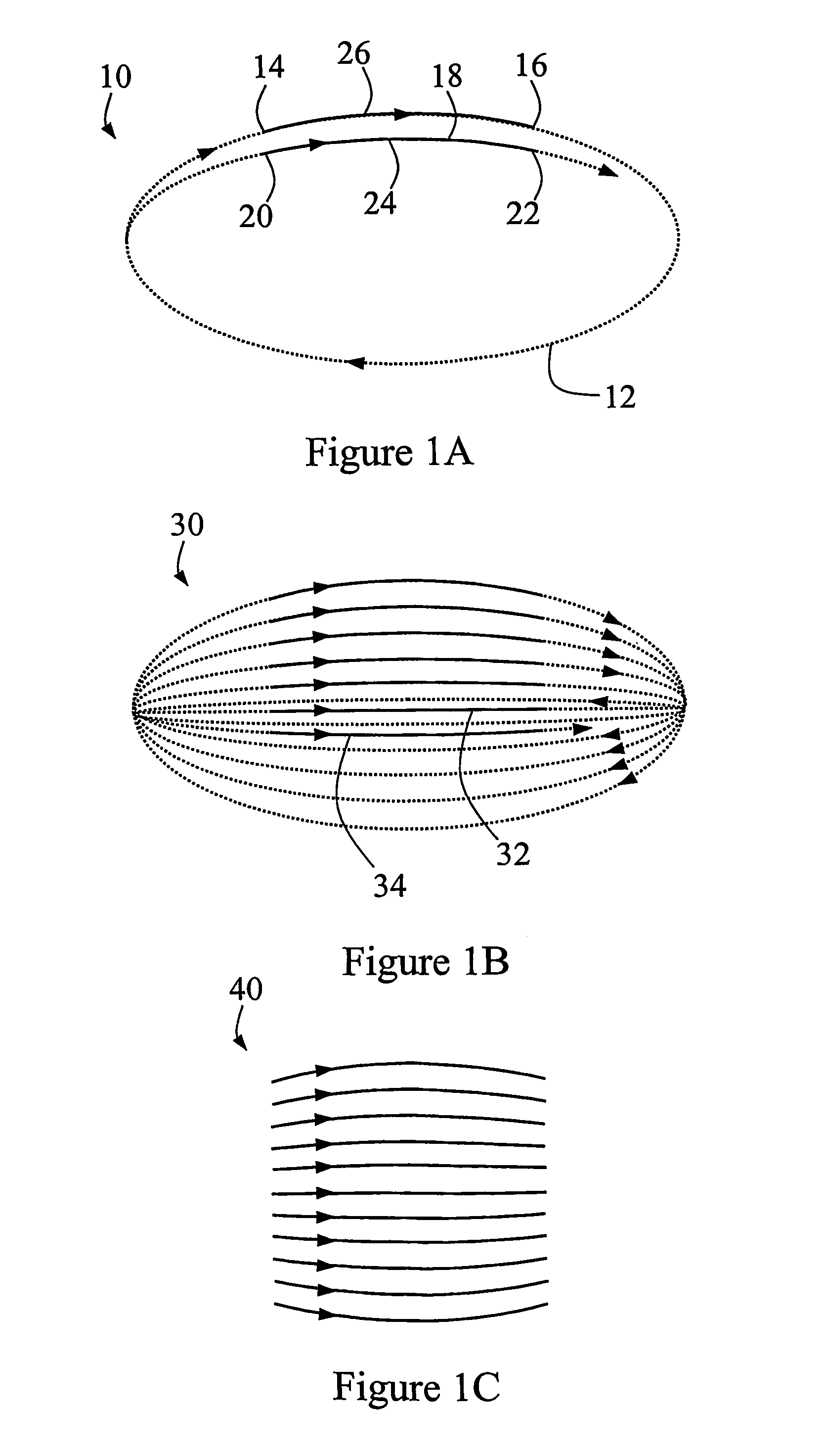
[0083]An elliptical scan pattern according to a first preferred embodiment of the present invention is shown, soon after commencement, at 10 in FIG. 1A. In this figure (and in FIGS. 1B and 1C), a broken curve indicates those portions of this scan where no data acquisition is occurring; a solid curve indicates data acquisition.

[0084]The scan traces out a first ellipse 12 with a major axis twice the length of its minor axis (that is, with an eccentricity of approximately 0.87).

[0085]When the scan reaches the top, central region of ellipse 12 (that is, at point 14 to the left of the minor axis) data acquisition is triggered and continues to a comparable point 16 to the right of the centre of the ellipse 12 at which data acquisition is stopped. Thus, data is acquired over an arc with a length approximately equal to the semi-major axis of the ellipse 12. Although this arc has some curvature, this does not lead to an excessive level of distortion if processed as though it were straight. I...


PUM


Abstract

A scanning apparatus and method, the apparatus comprising: a light transmission means (90) having an exit tip; first and second drive means (92,94) for resonantly driving the light transmission means (90) in orthogonal directions; wherein the first and second drive means (92,94) are operable to move the tip in an elliptical pattern while varying the eccentricity of the elliptical pattern, whereby a portion of the elliptical pattern having a centre on the minor axis of the elliptical pattern approximates—at least in appearance—a raster pattern.

Description

FIELD OF THE INVENTION[0001]The present invention relates to a scanning method and apparatus, of particular but by no means exclusive application in scanning fibre microscope and scanning fibre endoscopes.BACKGROUND OF THE INVENTION[0002]One existing scanning technique employs a resonant cantilever in order to achieve the high frequency scanning of an optical fibre tip, as a compact alternative to resonant mirror / galvanometer scanners. The high frequency or X scan is then combined with a slow or Y scan to produce a standard raster scanning pattern. The slow scan is usually not resonant and can have a sawtooth function, with relatively rapid retrace.[0003]In such an arrangement, mechanical considerations require a resonant sinusoidal spot motion in the X or fast direction of the scan. Although a TV raster in both directions is more desirable (for optical dosage control and data gathering), a sawtooth scan at constant speed is feasible in only the slow or Y direction. As shown in FIG....

Claims


Application Information

Patent Timeline
Patent Type & Authority Patents(United States)
IPC IPC(8): G02B6/26G02B26/08G01Q10/06G02B21/00G02B23/24
CPCB82Y35/00G01Q10/06G02B6/3504G02B6/3572G02B21/002G02B23/2407G02B26/101G02B26/103G02B2006/0098
Inventor ROSMAN, GAVAN EDMUNDBYRNE, CHRISTOPHER GERARDJONES, BRADLEY CHARLES
Owner OPTISCAN
Why Eureka
Try Eureka