Bi-directional equal force log splitter

a bi-directional, equal force technology, applied in the field of bi-directional log splitters, can solve the problems of slow bi-directional log splitters, inability to meet the production methods and quantities required, so as to increase the production of log splitters, increase production, and increase production

Active Publication Date: 2006-10-24
MARX DANIEL A
View PDF18 Cites 7 Cited by
  • Summary
  • Abstract
  • Description
  • Claims
  • Application Information

AI Technical Summary

Benefits of technology

[0011]In accordance with the above advantages and objects, the present invention discloses a bi-directional log-splitting device exhibiting equal lateral forces in both directions in order to increase production in log splitting operations. A pair of hydraulic cylinders is utilized on the log-splitting device to provide equal forces in either direction with the same degree of compressibility when the logs are split. In order to further increase production, a four-way star-shaped splitting head may also be utilized on both ends of the log splitter, so that each log may be split into four pieces, thereby further increasing production. The use of two double-acting cylinders means that the log splitter is able to push and pull the ram at the same time, thereby adding to the degree of compressibility, and increasing the certainty of the log splitting effect itself. The configuration of the log splitter and its commensurate guide rods yield a log-splitting device with a minimal leverage effect, unlike those in the prior art. This feature will furthermore increase the productivity of the log-splitting device, and it is described more fully hereinbelow.

Problems solved by technology

However, these log-splitting devices were slow, and were not amenable to production methods and quantities required because each log required a single stroke of the ram, and the ram needed to be returned to the original position.
These bi-directional log-splitting devices did not meet with much success, because the forces of the hydraulic ram were greater in one direction than in the other.
Needless to say, this is cumbersome and unwieldy.

Method used


Image

  • Bi-directional equal force log splitter
  • Bi-directional equal force log splitter
  • Bi-directional equal force log splitter

Examples


Embodiment Construction

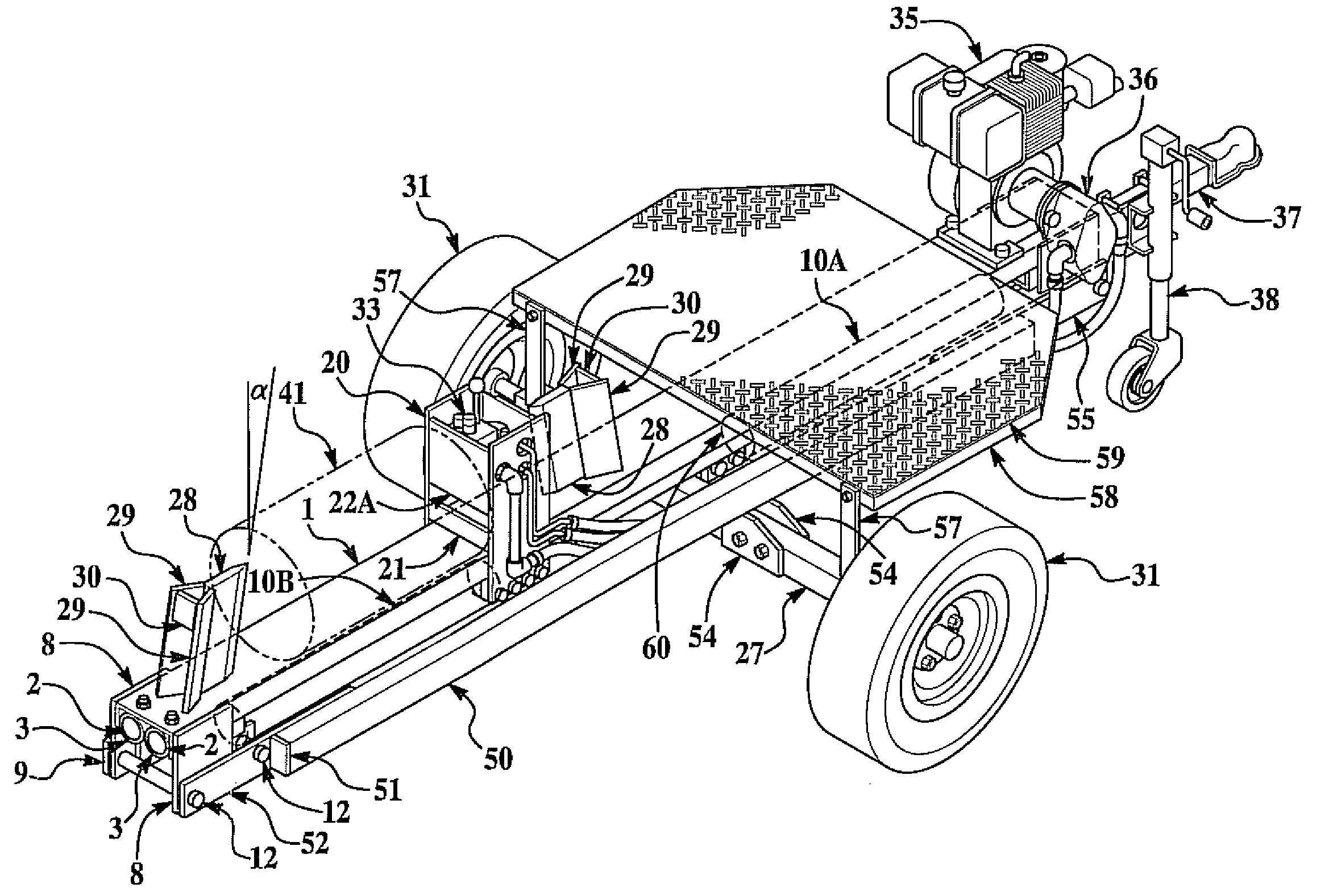
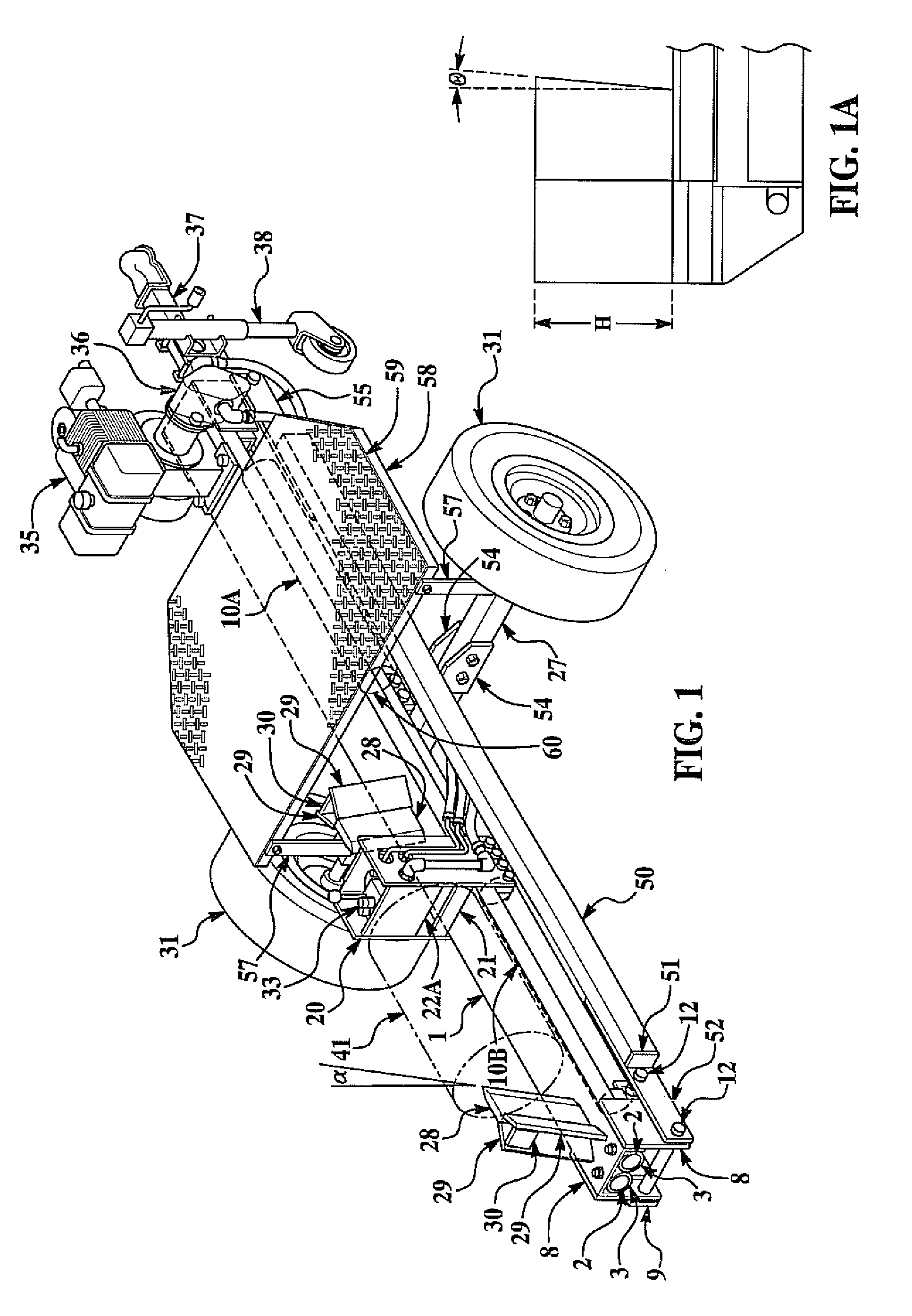
[0029]Looking first to FIG. 1, there is shown a bi-directional log splitter made in accordance with the present invention, which includes the log-splitting device mounted on an axle and wheels and being hydraulically activated to split logs in either direction.

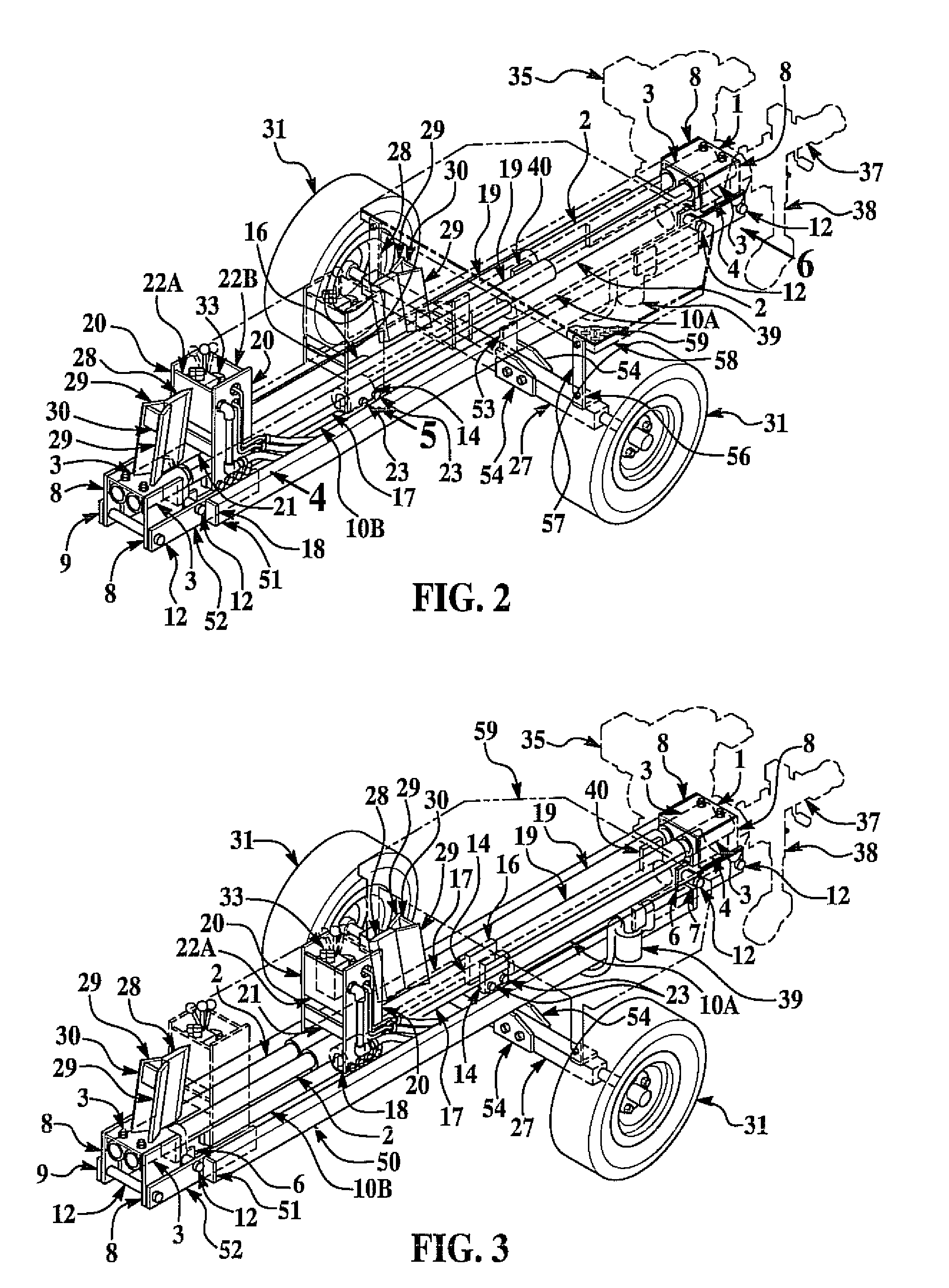
[0030]Main beam 1 acts as a support for the logs and is resting on top of guide rods 2, which are held in place by guide rod anchors 3. Guide rods 2 are straddled by strut plates 8, which are used for securing a pair of strut arms 9. In between the pair of strut arms 9 is located the first and second hydraulic cylinders 10A and 10B. Strut arms 9 are held in place by strut arm locator pins 12 to yield a rigid substructure for the entire log-splitting device. Looking now to the hydraulic ram which is generally denoted by the numeral 20, the ram includes a skid plate 21 and a valve locator plate 22A against which log 41 is placed in order to come into contact with splitting wedge 28. Attached to splitting wedge 28 are splitting w...


PUM


Abstract

A bi-directional log splitter having at least two stationary splitting wedges and a moveable ram therebetween for splitting wood, said splitter being mounted on a trailer where the splitter exerts a substantially equal force for both the exertion and the retraction strokes to increase the production of split wood.

Description

CROSS REFERENCES TO RELATED APPLICATIONS[0001]This application claims the benefit of U.S. Provisional Application No. 60 / 405,042 filed on Aug. 21, 2002.TECHNICAL FIELD[0002]This invention relates generally to log splitters, and more particularly to a bi-directional log splitter which can split logs in both directions with equal force.BACKGROUND OF THE INVENTION[0003]Log splitting has been going on as long as man has been burning wood for fire. Until recently, logs were either split by hand using an ax, or using a pneumatic or hydraulic log splitter. The earliest log splitters were single direction log splitters, where a log was placed near a wedge and a ram pushed the log against the wedge, thereby splitting the log. However, these log-splitting devices were slow, and were not amenable to production methods and quantities required because each log required a single stroke of the ram, and the ram needed to be returned to the original position. In the spirit of increasing production, ...

Claims


Application Information

Patent Timeline
Patent Type & Authority Patents(United States)
IPC IPC(8): B27L7/06B27L7/00
CPCB27L7/00B27L7/06
Inventor MARX, DANIEL A.
Owner MARX DANIEL A
Why Eureka
Try Eureka