Light-emitting unit

a technology of light-emitting units and light-emitting components, which is applied in the direction of semiconductor devices for light sources, light source combinations, fixed installations, etc., can solve the problems of large height gaps between devices, unsuitable devices for such applications, and considerable work required on devices, so as to improve the safety of people walking and enhance the appearance

Inactive Publication Date: 2006-10-24
B SURE CO USA
View PDF5 Cites 52 Cited by
  • Summary
  • Abstract
  • Description
  • Claims
  • Application Information

AI Technical Summary

Benefits of technology

[0046]According to the light-emitting unit given by this invention, a space is created between the casing and mounting surface by the spacer, while the power terminal and signal terminal are located on the rear face of the casing. Therefore, even when multiple light-emitting units are conn...

Problems solved by technology

However, the above light-emitting device is buried in a floor of a building and therefore generally installed during the construction of the building.
Considerable work is required if the device is to be installed in an existing floor.
Therefore, the conventional light-emitting devices could not promptly satisfy the needs for producing artistic or decorative effects using light only during an event held in a store or specific program presented in an exhibition venue, and the prohibitive construction expenses required to install this type of light-emitting device also made the device unsuitable for such applications.
This not only limits the location for installing alighting device in terms of the height of the ceiling or entrance/exit, but it also creates a large height gap between the sections where a lighting device is installed and not installed, thereby posing a concern over stepping up/down the device by people walking on top.
As a result, it is not possible to emit a desired color or change the color with the passage of time.
Consequently, this lighting device could not fully produce a full-scale light fantasy or illusion, either, to arouse excitement in the customers.
This made the wiring of power cables more complex, reduces the aesthetic effects, and sometimes made it difficult to interconnect the lighting devices.
In addition, the reinforced plastic material installed in the top opening of the casing scratches easily due to contact with the edge of a heal or umbrella worn/held by people walking on top, and the scratched areas tend to become clouded.
For this reason, there arise concerns that transparency would be lost with the passing of time, thereby making the illumination look darker...

Method used


Image

  • Light-emitting unit
  • Light-emitting unit
  • Light-emitting unit

Examples


Embodiment Construction

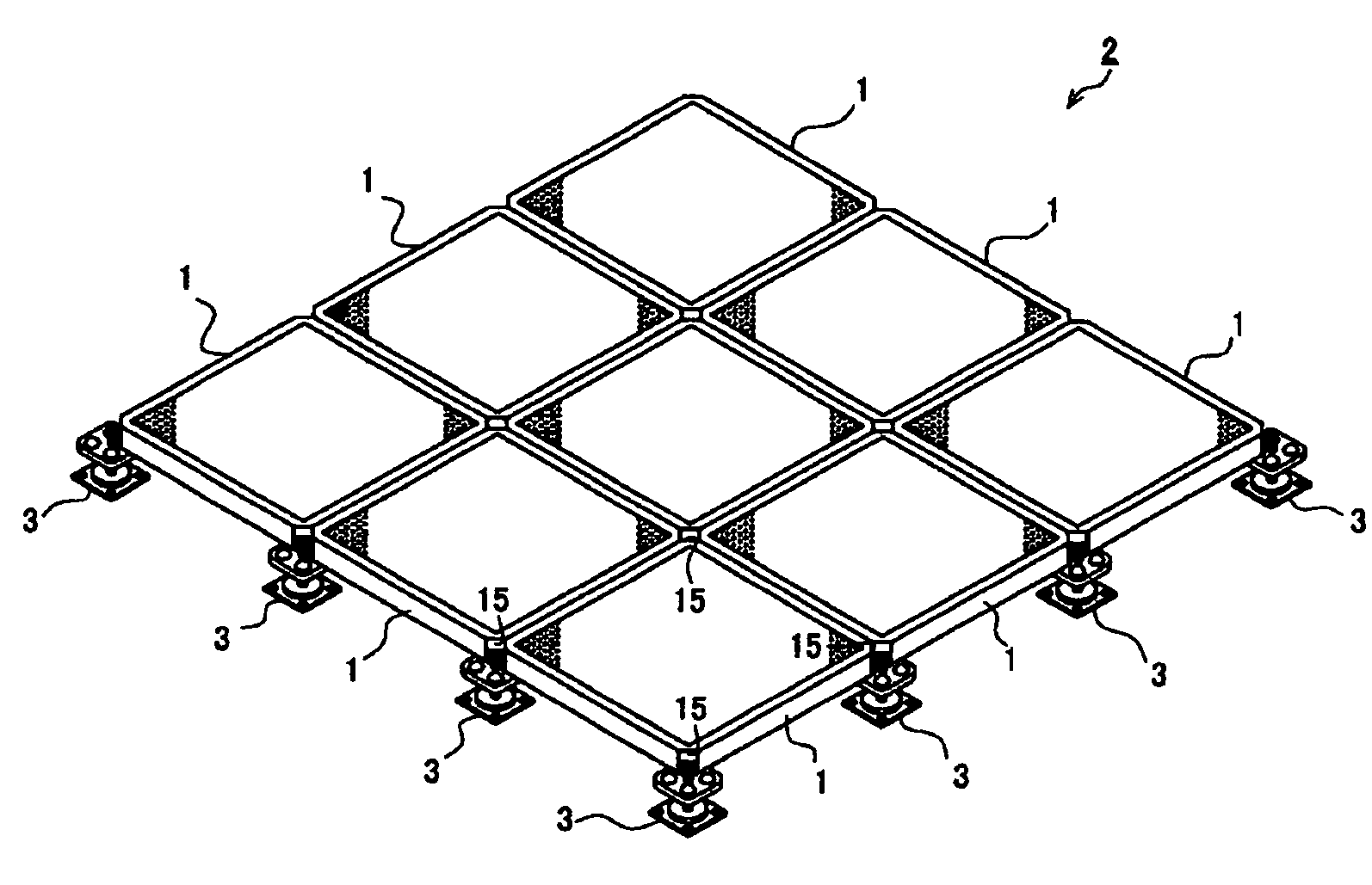
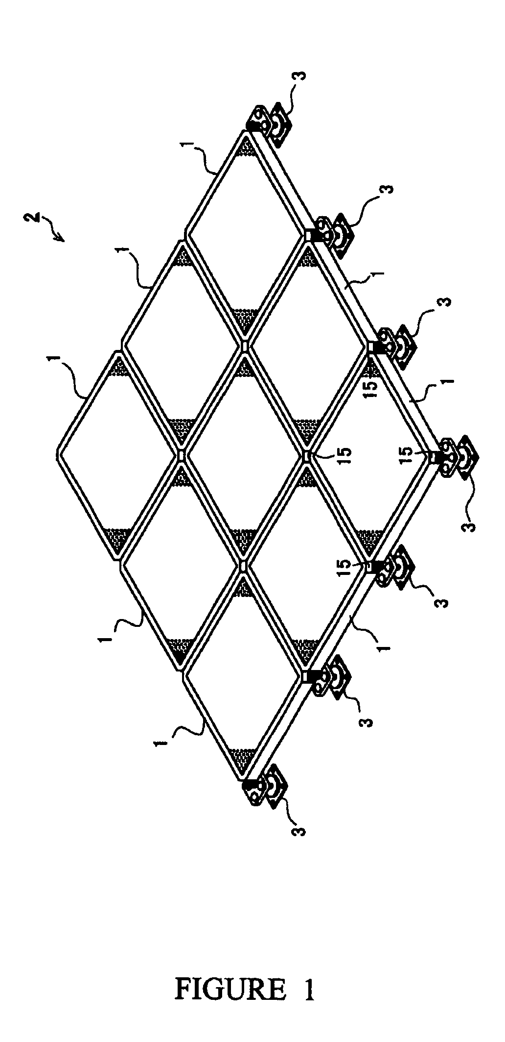
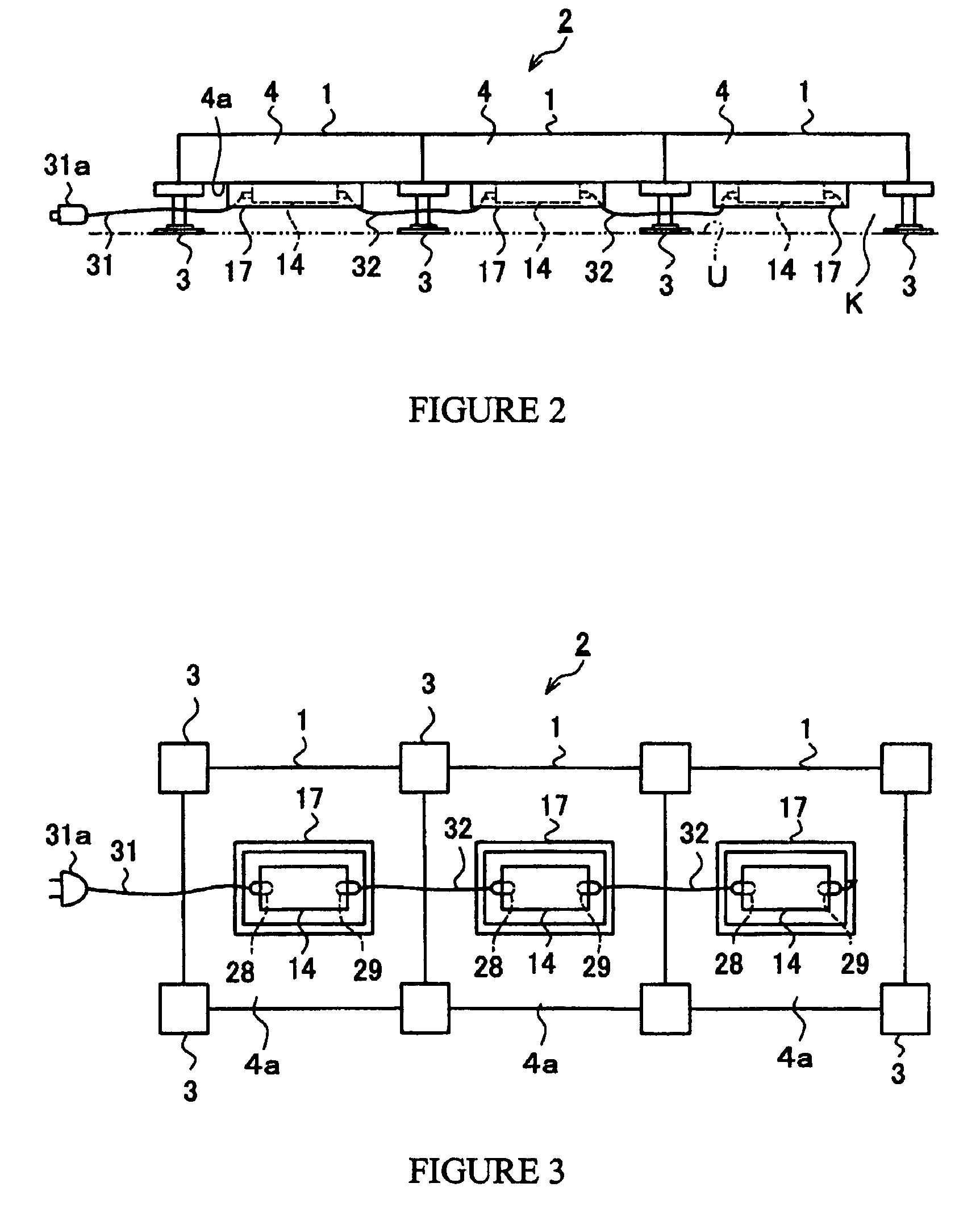
[0066]An embodiment of the surface light-emitting unit 1 given by the present invention is explained according to FIGS. 1 through 9. FIGS. 1 through 3 provide a perspective view, side view and bottom view of a floor lighting system 2 combining multiple surface light-emitting units 1, while FIG. 4 gives an exploded perspective view of the surface light-emitting unit 1. FIG. 5 is a section view illustrating the structure of key parts of the surface light-emitting unit 1, FIG. 6 is an explanation drawing showing the arrangement of light-emitting diodes, FIG. 7 gives a circuit diagram for the control unit, and FIG. 8 provides a flow chart illustrating the flow of operations. FIG. 9 provides an enlarged perspective view illustrating the structure of the base metal.

[0067]The floor lighting system 2 given in this example combines multiple surface light-emitting units 1 on a flat surface, as shown in FIGS. 1 through 3, and is installed on a floor U of a structure, for example. FIG. 1 illust...


PUM


Abstract

A surface light-emitting unit installed on a floor or wall of a structure is able to emit light from its surface for unique illumination effects. A surface light-emitting unit includes a transparent glass plate that can transmit light; a light-conducting plate installed below the glass plate; a light-emitting means having multiple light-emitting diodes of different colors and installed on the side face of the light-conducting plate; a light-diffusing/reflecting member installed below the light-conducting plate that diffuses and reflects the light; an emission-color selection means for selecting the light-emitting diode to be illuminated or blinked; a casing for providing the transparent glass plate at the top opening; a casing for installing above components; and a connection part that can be connected to other surface light-emitting unit installed adjacently.

Description

LIGHT-EMITTING UNIT[0001]This application claims foreign filing priority upon Japanese patent application Ser. No. 2003-154048 filed on May 30, 2003. The contents of which are all herein incorporated by reference in their entireties.FIELD OF THE INVENTION[0002]This invention relates to a surface light-emitting unit, specifically a surface light-emitting unit installed along a floor or wall of a structure and is able to emit light from its surface.BACKGROUND OF THE INVENTION[0003]Flush-type light-emitting devices that are embedded in a floor of a store, restaurant, etc., and emit light from its surface (top surface) are known. This type of light-emitting device is able to produce artistic and decorative effects using light and give visual entertainment to the customers, etc.[0004]However, the above light-emitting device is buried in a floor of a building and therefore generally installed during the construction of the building. Considerable work is required if the device is to be ins...

Claims


Application Information

Patent Timeline
IPC IPC(8): F21S8/00E04F15/18E04F15/02F21S10/00F21S10/02F21V8/00F21W121/00F21Y101/02G02B6/00G09F13/00G09F13/18G09F13/20H05B37/02
CPCE04F2290/026F21S8/032F21S10/02F21Y2105/00F21V2200/20F21Y2113/13F21Y2115/10G02B6/0036G02B6/0051G02B6/0055G02B6/0068G02B6/0078G02B6/0083G02B6/0086Y10S362/80E04F15/02G09F13/20
Inventor KITAJIMA, SHIGEMASATAKAHASHI, SHINOBUITO, KYOSUKE
Owner B SURE CO USA
Why Eureka
Try Eureka