Reformer exercise apparatus having a trapeze bar

Inactive Publication Date: 2006-10-24
BALANCED BODY INC
View PDF54 Cites 85 Cited by
  • Summary
  • Abstract
  • Description
  • Claims
  • Application Information

AI Technical Summary

Benefits of technology

[0011]The trapeze assembly includes an upside down, generally U shaped arched frame having a spaced pair of parallel legs. Each leg is removably received in a T slot clamp bracket assembly that fastens the leg in the T slot. The U shaped trapeze frame may be pivoted in the bracket assemblies to a folded position so as to lie generally along the top of the reformer frame for compact storage, and

Problems solved by technology

One of the drawbacks, however,

Method used


Image

  • Reformer exercise apparatus having a trapeze bar
  • Reformer exercise apparatus having a trapeze bar
  • Reformer exercise apparatus having a trapeze bar

Examples


first embodiment

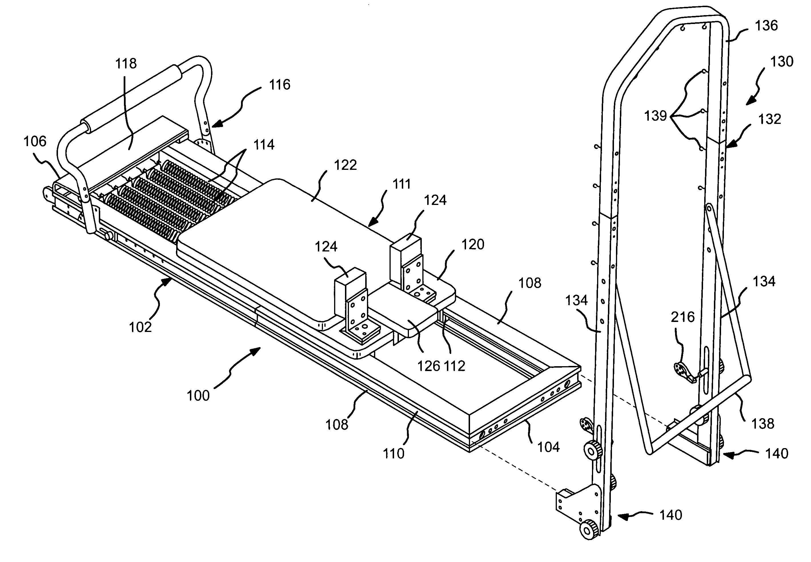
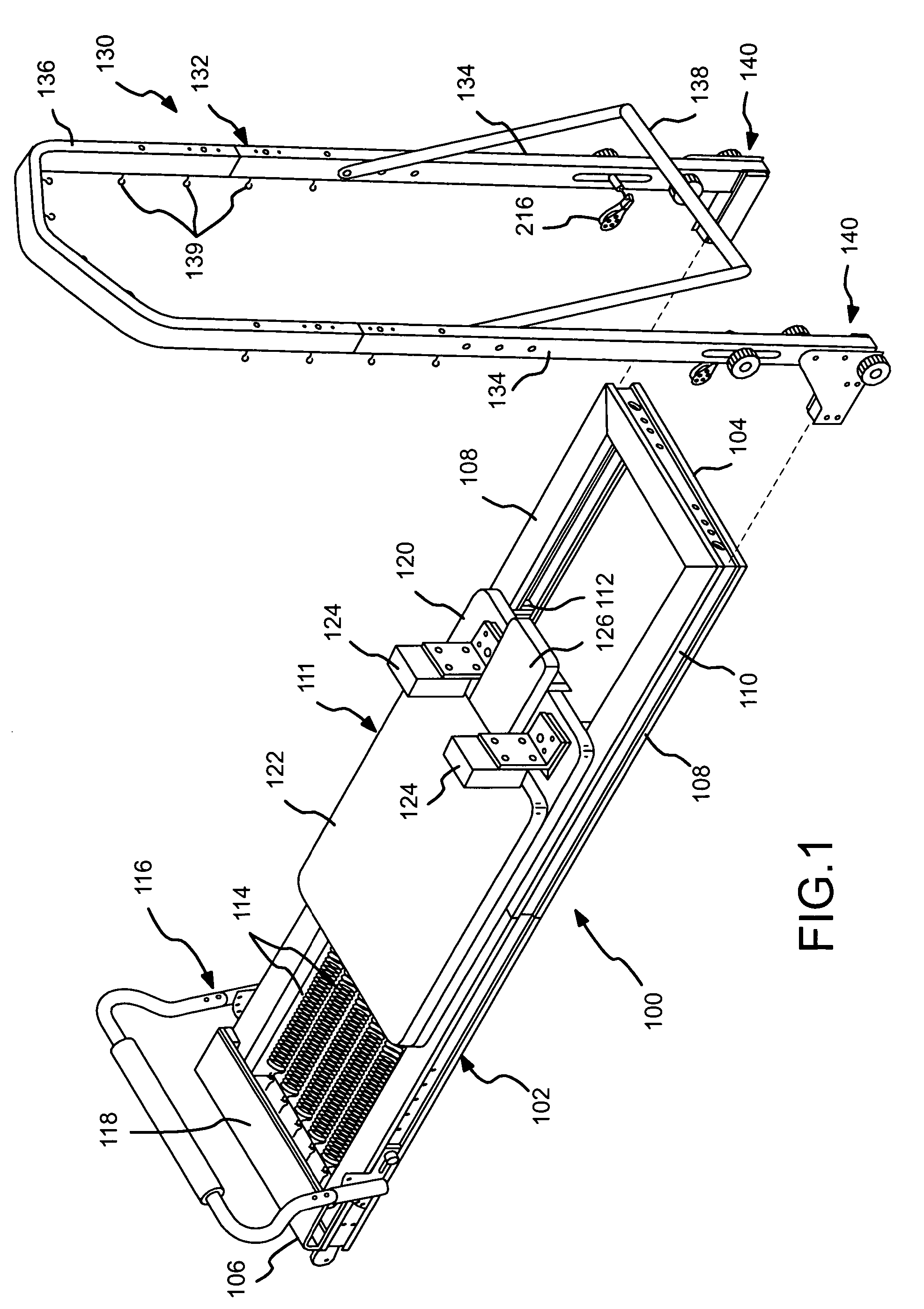
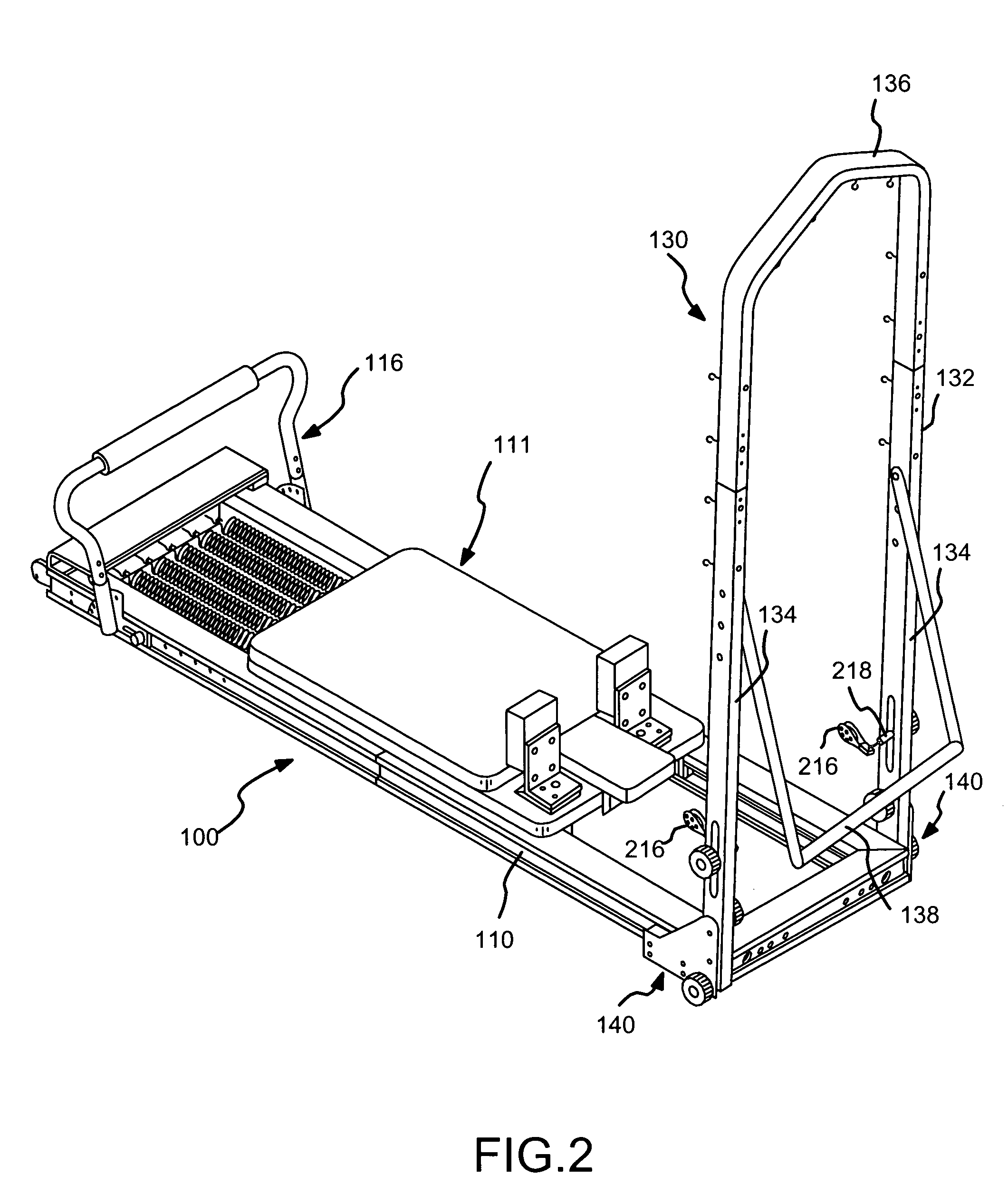
[0020]An exercise apparatus 100 in accordance with the present invention is shown in upper and lower perspective views in FIGS. 1 and 2 respectively. The exercise apparatus 100 comprises a generally rectangular frame 102 having a head end 104 and a foot end 106 and a pair of parallel track or rail members 108 separating the head end 104 from the foot end 106. Each of the rail members 108 has an outwardly open T shaped slot 110 running the length of the rail member 108.

[0021]A movable carriage 111 rides on four roller / guide wheel assemblies 112, one of which can barely be seen in FIG. 1, fastened to the underside of the carriage 111. These wheel assemblies 112 roll on the track members 108 to support and guide movement of the carriage 111 back and forth along the track members 108 of the frame 102. A plurality of elastic members, e.g., springs 114 are selectively connected between the carriage 111 and the foot end 106 to bias the carriage 111 toward the foot end 106.

[0022]A foot bar ...

embodiment 140

[0034]In the embodiment 140 shown in FIG. 7, the elongated pivot washer plate 154 is fastened to the outer plate 146 with three screws 164. These screws form a rigid connection between the outer plate 146 and the washer plate 154. Washer plate 154 has an upper threaded hole 166 that aligns with bore 168 through the outer plate 146. This hole 166 receives the distal end of the bolt 150. The bore 168 acts as a clearance passage for the end of the bolt 150.

[0035]Each of the frame legs 134 is a square tube. The lower end of each of the trapeze frame legs 134 has a pair of open slots 170 in opposite sides of the square tube end. A first pair of closed slots 172 in the same opposite sides of the square tube frame legs 134 is spaced from the slots 170. A second pair of closed slots 174 is spaced axially from the first pair of closed slots 172. The upper clamp bolt 150 passes through a spacer 182 and through the lower closed slots 172, threads into the threaded hole 166 in the washer plate ...


PUM


Abstract

A reformer exercise apparatus comprises a rectangular frame, a movable carriage mounted on the frame for supporting a user an elongated elastic member extending between the frame and the movable carriage for biasing the carriage toward the one end of the frame, and a U shaped trapeze bar assembly removably fastened to the reformer frame via outwardly open T shaped slots in each reformer frame rail. The trapeze assembly includes a support bracket assembly slidably disposed in the slot to fasten a trapeze leg to the reformer frame. the support bracket assembly permits the trapeze assembly to be folded parallel to the reformer frame for storage and transport, and rigidly fastened to the reformer frame in an upright position during use.

Description

CROSS REFERENCE TO RELATED APPLICATIONS[0001]This application is a continuation-in-part of U.S. patent application Ser. No. 10 / 723,407, filed Nov. 25, 2003. This application is also a continuation-in-part of U.S. patent application Ser. No. 10 / 438,579, filed on May 14, 2003 now U.S. Pat. No. 6,971,976, which is a continuation of U.S. patent application Ser. No. 10 / 035,842, filed on Dec. 24, 2001 now U.S. Pat. No. 6,926,650, which is a continuation-in-part of U.S. patent application Ser. No. 09 / 835,204, filed on Apr. 12, 2001, now U.S. Pat. No. 6,527,685, which is a continuation-in-part of U.S. patent application Ser. No. 09 / 521,555, filed on Mar. 9, 2000, now U.S. Pat. No. 6,371,895, which is a continuation-in-part of U.S. patent application Ser. No. 09 / 275,755, filed Mar. 25, 1999, now U.S. Pat. No. 6,186,929 which is also a continuation-in-part of U.S. patent application Ser. No. 09 / 266,286, filed Mar. 11, 1999, now abandoned, all of which are hereby incorporated by reference in t...

Claims


Application Information

Patent Timeline
IPC IPC(8): A63B26/00A63B21/00A63B21/02A63B21/055A63B23/035A63B23/04A63B23/12
CPCA63B21/023A63B21/154A63B22/0087A63B23/0355A63B23/0405A63B22/203A63B21/00065A63B21/0428A63B21/0442A63B21/055A63B22/0023A63B23/03575A63B23/12A63B2023/0411A63B2208/0204A63B2208/0228A63B2208/0247A63B2208/0252A63B2208/0257A63B2210/50A63B23/03525A63B21/4029A63B21/4033A63B21/4034A63B21/4035A63B21/4045
Inventor ENDELMAN, KEN
Owner BALANCED BODY INC
Why Eureka
Try Eureka