Vertical split gate memory cell and manufacturing method thereof

a technology of vertical split gate and memory cell, which is applied in the direction of solid-state devices, semiconductor devices, instruments, etc., can solve the problems of slowing down the road map of high-density non-volatile memory, unsatisfactory low-power devices, and rather complex processes, and achieves low-power devices, high degree of integration, and easy manufacturing

Active Publication Date: 2006-10-24
SKYMEDI CORPORATION
View PDF4 Cites 26 Cited by
  • Summary
  • Abstract
  • Description
  • Claims
  • Application Information

AI Technical Summary

Benefits of technology

[0009]The objective of the present invention is to provide a vertical split gate memory cell for low power device applications and high degree integration. In addition, the vertical split gate memory cell can be more easily manufactured, so the cost is lowered.

Problems solved by technology

With the development of a high degree integration on a substrate, scaling down a non-volatile memory cell is rather hindered due to inherent dimensions of source, drain and gate channel thereof, so the roadmap of high density non-volatile memory may slow down significantly.
Further, a conventional non-volatile memory cell normally needs high currents to operate, e.g., 200 microamperes (μA), for hot electron programming, so it is not satisfactory for low power devices that comply with the tendency for chip development.
Accordingly, a second deep trench is formed to modulate a second portion of the channel and form a series transistor, which really leads to a rather complex process.
However, the split gate voltage is not operated independently, despite the fact that the control gate voltage can turn on the floating gate and split gate transistors effectively, electrons may jump into the floating gate as well as the control gate owing to high bias voltages generated both in the floating gate and in the control gate.
Accordingly, although this approach may reduce process complexity, electron injection efficiency during programming may not be optimized.
Since gate voltage of the select transistors is always coupled from control gate and cannot be independently adjusted, low programming efficiency or electrons trapped in the ONO layers may be created instead.

Method used


Image

  • Vertical split gate memory cell and manufacturing method thereof
  • Vertical split gate memory cell and manufacturing method thereof
  • Vertical split gate memory cell and manufacturing method thereof

Examples


Embodiment Construction

[0021]Embodiments of the present invention are now being described with reference to the accompanying drawings.

[0022]A process for making a vertical split gate memory cell of NMOS type is exemplified as follows, with a view to illustrating the features of the present invention.

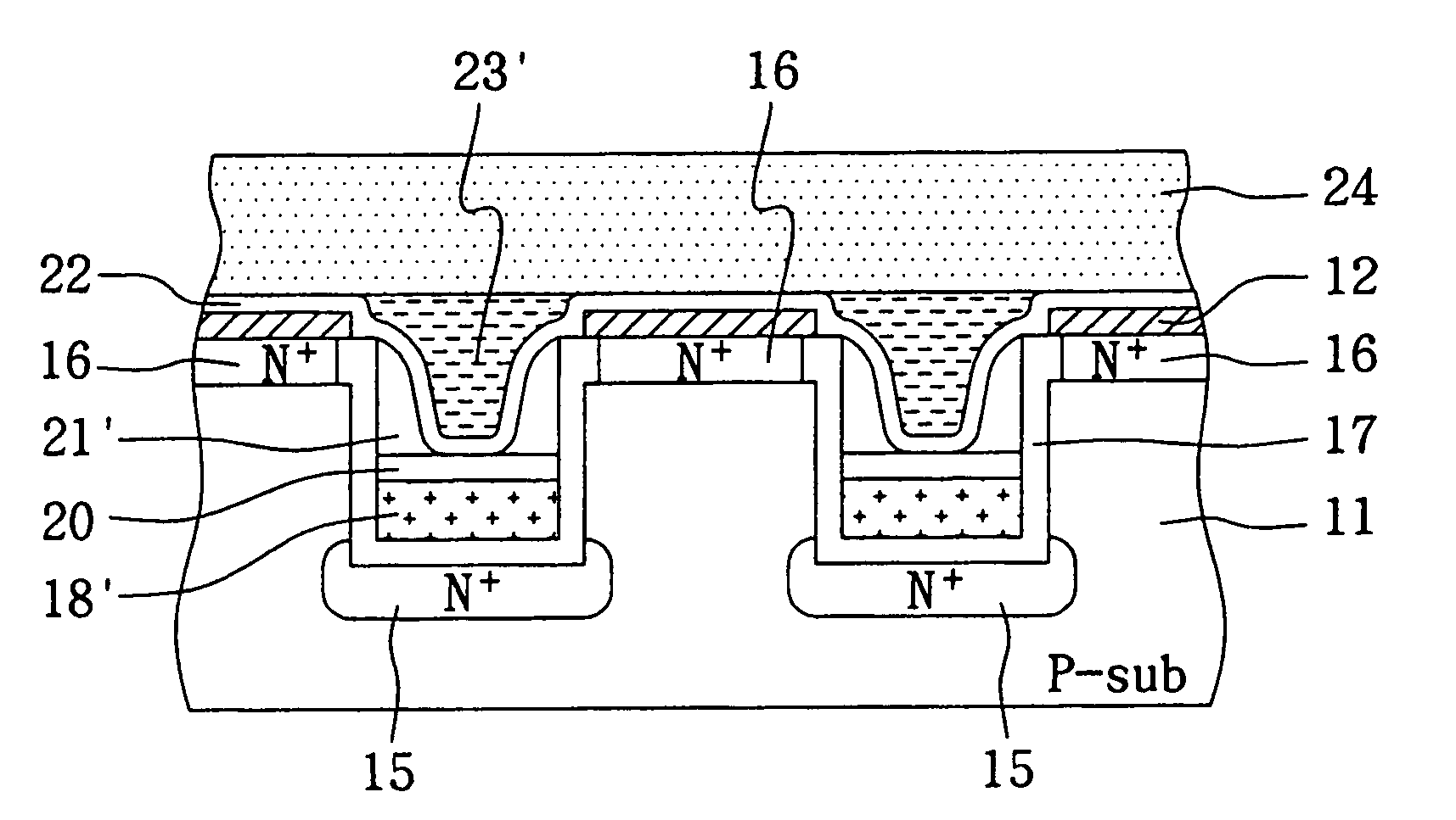
[0023]FIGS. 4 through 15 illustrate the memory structures of each step in the manufacturing of a non-volatile vertical split gate memory cell put forth in the present invention. In FIG. 4, a mask layer 12 is formed on a surface of a semiconductor substrate 11, e.g., a silicon substrate, where the mask layer 12 is typically of a thickness between 100–2000 angstroms, and can be composed of silicon nitride (SixNy), silicon oxide (SiOx), silicon oxynitride (SiOxNy) or multi-layer of these films. Then, a photoresist layer 13 is deposited on the surface of the mask layer 12, and is patterned to define multiple trenches as shown in FIG. 5.

[0024]In FIG. 6, the mask layer 12 and the semiconductor substrate 11 are etche...


PUM


Abstract

A vertical split gate memory formed in a trench of a semiconductor substrate comprises a first doping region, a second doping region, a conductive line, a conductive spacer and a conductive plug, wherein the conductive line, conductive spacer and conductive plug serve as a select gate, a floating gate and a control gate of the vertical split gate memory cell, respectively. The first doping region of a first conductive type is underneath the bottom of the trench, whereas the second doping region of the first conductive type is beside the top of the trench. The conductive line serving as the select gate is formed at the bottom of the trench and in operation relation to the first doping region. The conductive spacer is formed beside the sidewall of the trench and above the conductive line. The conductive plug is insulated from the conductive spacer and the conductive line and in operation relation to the conductive spacer.

Description

BACKGROUND OF THE INVENTION[0001](A) Field of the Invention[0002]The present invention is related to a non-volatile memory cell and the manufacturing method thereof, and more particularly to a vertical split gate memory cell and the manufacturing method thereof.[0003](B) Description of the Related Art[0004]With the development of a high degree integration on a substrate, scaling down a non-volatile memory cell is rather hindered due to inherent dimensions of source, drain and gate channel thereof, so the roadmap of high density non-volatile memory may slow down significantly. Accordingly, development of small memory cell is crucial for the next generation, and thus vertical memory cells have been attracting much attention recently.[0005]Wong et al. disclosed a non-volatile memory cell of vertical floating gates in U.S. Pat. No. 5,739,567. FIG. 1 shows a vertical memory cell 500 disclosed by Wong et al., where channel regions 503 are formed on top of a source region 502, and drain re...

Claims


Application Information

Patent Timeline
Patent Type & Authority Patents(United States)
IPC IPC(8): H01L29/76G11C16/04H01L21/28H01L21/336H01L21/8247H01L29/423H01L29/788H01L29/94
CPCH01L21/28273H01L27/11556H01L29/42328H01L29/42336H01L29/66825H01L29/7887G11C16/0433G11C16/0466H01L29/42344H01L29/42352H01L29/40114H10B41/27
Inventor SHONE, FUJA
Owner SKYMEDI CORPORATION
Why Eureka
Try Eureka