Automotive vehicle electrical system diagnostic device

a technology for automotive vehicles and diagnostic devices, which is applied in the direction of exchanging data chargers, transportation and packaging, instruments, etc., can solve the problems of failures or symptoms related to such failures, can be intermittent and difficult to identify, and can fail completely or decay with tim

Inactive Publication Date: 2006-10-24
MIDTRONICS
View PDF387 Cites 141 Cited by
  • Summary
  • Abstract
  • Description
  • Claims
  • Application Information

AI Technical Summary

Problems solved by technology

The storage batteries and electrical systems of such automotive vehicles can fail completely or decay with time.
Further, failures or symptoms related to such failures, can be intermittent and difficult to identify.

Method used


Image

  • Automotive vehicle electrical system diagnostic device
  • Automotive vehicle electrical system diagnostic device
  • Automotive vehicle electrical system diagnostic device

Examples


Embodiment Construction

[0016]The present invention includes an apparatus and method for testing a battery and / or electrical system of an automotive vehicle using a diagnostic device which is temporarily coupled to the electrical system of the vehicle. While the device is coupled to the vehicle, the vehicle can be driven such that data can be collected while the vehicle undergoes normal operation. The diagnostic device is removed from the vehicle after the testing period and during normal operation. Data collected by the diagnostic device while testing can then be observed or otherwise analyzed in order to identify failures or symptoms of failures in the electrical system and / or battery of the vehicle.

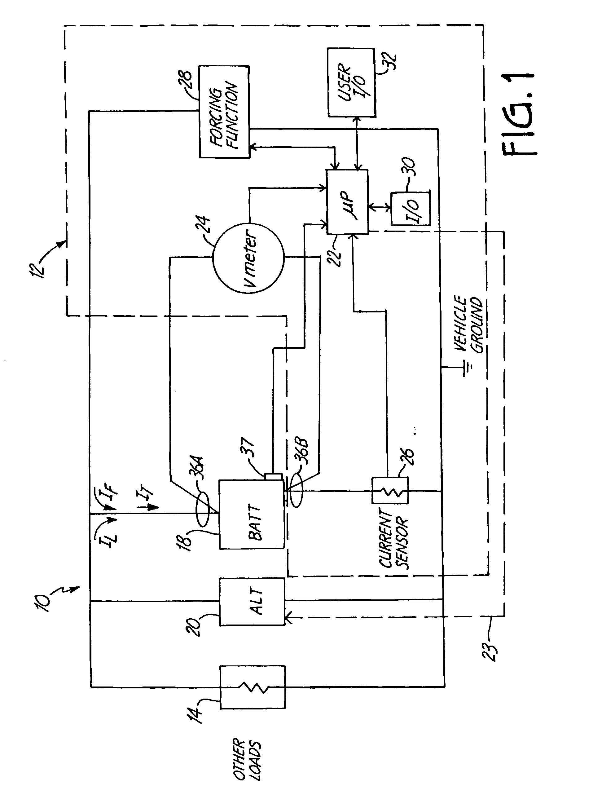
[0017]FIG. 1 is a simplified block diagram showing an automotive vehicle 10 which includes a battery monitor 12 in accordance with one embodiment of the present invention. Vehicle 10 includes vehicle loads 14 which are shown schematically as an electrical resistance. A battery 18 is coupled to the vehicle loa...


PUM

PropertyMeasurementUnit
voltageaaaaaaaaaa
open-circuit voltageaaaaaaaaaa
resistanceaaaaaaaaaa

Abstract

An automotive vehicle electrical system diagnostic apparatus includes first and second electrical connections configured to electrically couple to an electrical system of an automotive vehicle which includes a battery. Digital samples are obtained during operation of the vehicle which are related to the system. The digital samples are stored in memory.

Description

[0001]The present application is a Continuation-in-Part of application Ser. No. 10 / 046,659, filed Oct. 29, 2001 now U.S. Pat. No. 6,909,287 which is a divisional of application Ser. No. 09 / 564,740, filed May 4, 2000, now U.S. Pat. No. 6,331,762, which claims priority to Provisional Application Ser. No. 60 / 132,622, filed May 5, 1999, and entitled AUTOMOTIVE VEHICLE BATTERY CHARGING SYSTEM; U.S. Provisional Application No. 60 / 165,208, filed Nov. 12, 1999, and entitled ENERGY MANAGEMENT SYSTEM FOR AUTOMOTIVE VEHICLE; and Provisional Application Ser. No. 60 / 175,762, filed Jan. 12, 2000, and entitled ENERGY MANAGEMENT SYSTEM FOR AUTOMOTIVE VEHICLE, application Ser. No. 09 / 564,740 is also a Continuation-In-Part of application Ser. No. 08 / 962,754, filed Nov. 3, 1997, now U.S. Pat. No. 6,081,098, application Ser. No. 10 / 046,659 is also a Continuation-In-Part of application Ser. No. 09 / 575,627, filed May 22, 2000, now U.S. Pat. No. 6,313,608, which is a Continuation-In-Part of application Se...

Claims


Application Information

Patent Timeline
Patent Type & Authority Patents(United States)
IPC IPC(8): G01N27/416G01R31/00G01R31/36H02J7/00H02J7/16
CPCG01R31/3624G01R31/3627G01R31/3648H02J7/0004H02J7/0008H02J7/008H02J7/163G01R31/006G01R31/007G01R31/3675G01R31/3693Y02T10/7005G01R31/385G01R31/3647G01R31/3842G01R31/374H02J7/00041H02J7/00036H02J7/00047Y02T10/70H02J7/00712
Inventor BERTNESS, KEVIN I.SAMPSON, WILLIAM G.
Owner MIDTRONICS
Why Eureka
Try Eureka