Multifunctional optical device having a spatial light modulator with an array of micromirrors

a multi-functional, micromirror technology, applied in the direction of optical elements, multiplex communication, instruments, etc., can solve the problems of large diffraction loss and inability to plan channels independently

Inactive Publication Date: 2006-10-24
II VI DELAWARE INC
View PDF33 Cites 39 Cited by
  • Summary
  • Abstract
  • Description
  • Claims
  • Application Information

AI Technical Summary

Benefits of technology

[0011]The invention provides a new and unique reconfigurable multifunctional optical device comprising an optical arrangement for receiving at least one optical signal, each optical signal having one or more optical bands or channels, and a spatial light modulator for reflecting the at least one optical signal provided thereon. The optical arrangement features a free optics configuration with a light dispersion element for spreading each optical signal into one or more respective optical bands or channels for performing separate optical functions on each optical signal. In one embodiment, the spatial light modulator may include a micro-mirror device with an array of micro-mirrors, and the one or more respective optical bands or channels reflect off a respective plurality of micro-mirrors. In effect, the free optics configuration includes a common set of optical components for performing each separate optical function on each optical signal.
[0012]The separate optical functions reflect off separate non-overlapping areas on the spatial light modulator and may include different optical functions. The separate optical functions include optical switching, conditioning or monitoring functions such as either an optical add / drop multiplexer (OADM) function, an optical channel monitor (OCM) function, an optical cross-connect (CC) function, an optical interleaver / deinterleaver (INT / DEINT), a dynamic gain equalization filter (DGEF) or dynamic spectral equalizer (DSE), or some combination thereof. The at least one optical signal typically includes two or more optical input signals, on which a respective function is performed. The scope of the invention is also intended to include performing an optical function on one optical input signal, and performing a second optical function on the output signal from the first optical function.
[0013]The one or more light dispersion elements include either a diffraction grating, an optical splitter, a holographic device, a prism, or a combination thereof.
[0014]In accordance with an embodiment of the present invention, the multifunctional optical device may include a collimator that collimates a first and second optical input signal. Each of the first and second optical input signals includes a plurality of optical input channels. Each optical input channel is centered at a central wavelength. A light dispersion element substantially separates the optical channels of the collimated first and second input signals. A spatial light modulator reflects each of the first and second optical input channels along a respective first optical path or second optical path, in response to a control signal. The spatial light modulator comprises a micro-mirror device that includes an array of micro-mirrors selectively disposable between a first and a second position in response to the control signal. Each separated optical input channel of each of the first and second input signals is incident on a respective group of micro-mirrors. Each separated optical channel is incident on the respective group of micro-mirrors, wherein each respective separated optical input channel reflects along the respective first optical path when the micro-mirrors are disposed in the first position, or along the respective second optical path when the micro-mirrors are disposed in the second position. A controller generates the control signal in accordance with a switching algorithm.

Problems solved by technology

One issue with the above optical MEMs device is that it is not “channel plan independent”.
Another concern is that if the absolute value of a channel wavelength changes, a respective optical signal may begin to hit an edge of a corresponding mirror leading to large diffraction losses.

Method used


Image

  • Multifunctional optical device having a spatial light modulator with an array of micromirrors
  • Multifunctional optical device having a spatial light modulator with an array of micromirrors
  • Multifunctional optical device having a spatial light modulator with an array of micromirrors

Examples


Embodiment Construction

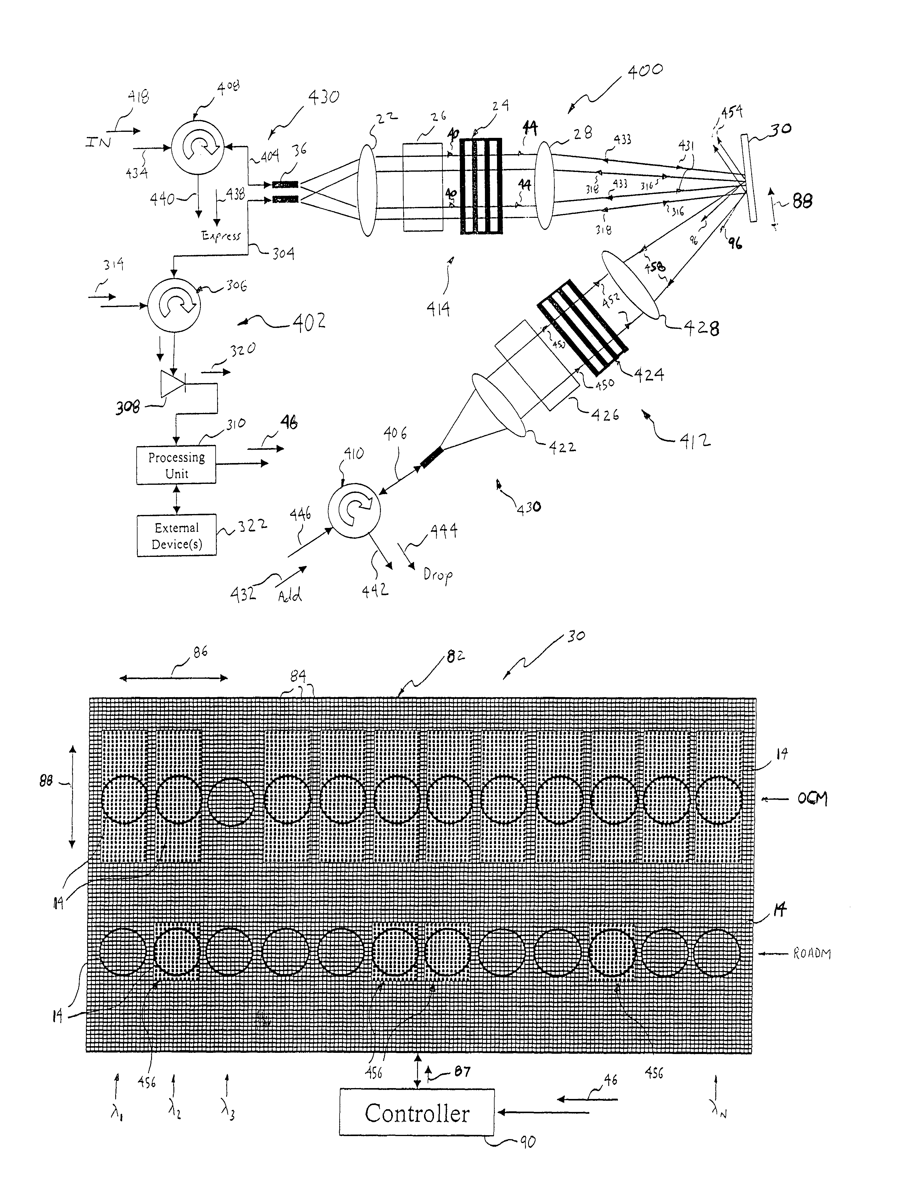
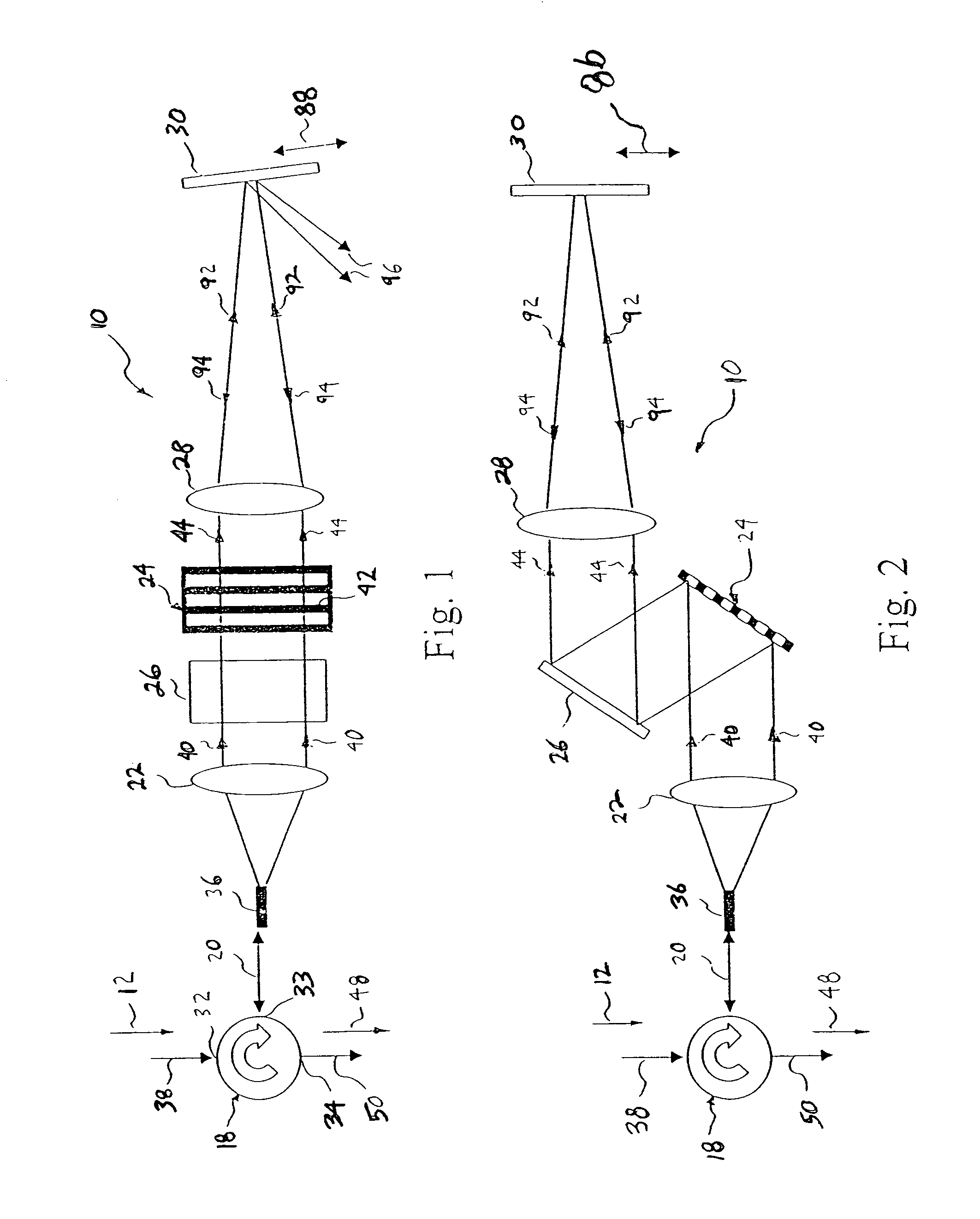
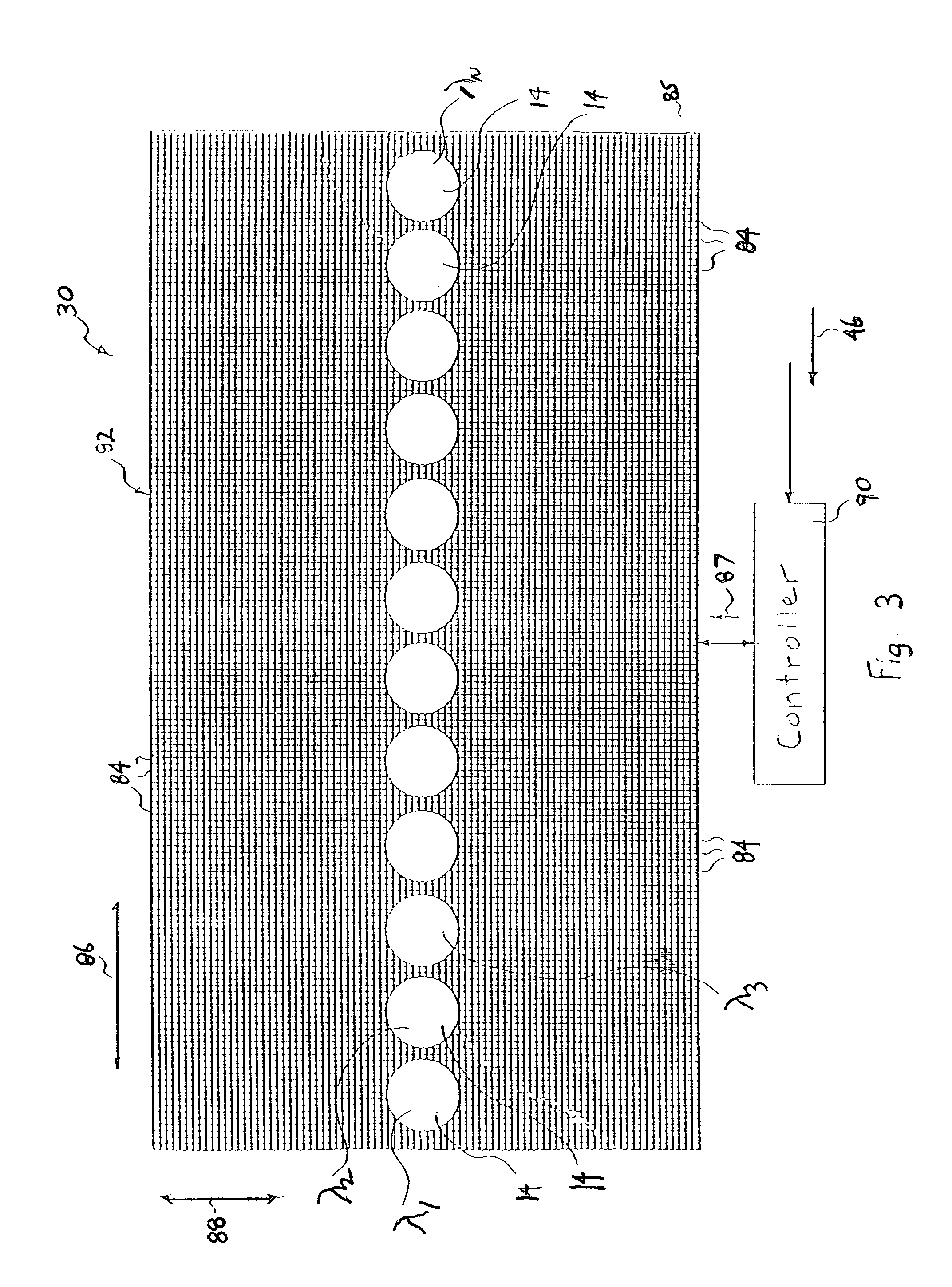
[0050]The present invention provides a multifunctional optical device that uses a single spatial modulator to provide multiple optical switching and / or conditioning of at least one optical input signal. For example, the optical device may function as both an optical filter and a reconfigurable optical add / drop device (ROADM). Another example is an optical device that may function as an optical channel monitor (OCM) and a dynamic gain equalizer filter (DGEF). In this manner, the functionality of the spatial light modulator can be efficiently utilized. To better understand the specific embodiments of the present invention, a reconfigurable optical filter 10 is first described in FIGS. 1–9, which has a substantial number of components common to the specific multifunctional embodiments.

[0051]Referring to FIGS. 1–3, the reconfigurable optical filter 10 selectively filters or attenuates a desired optical channel 14 of light (i.e., a wavelength band) of an optical WDM input signal 12. The ...


PUM


Abstract

A reconfigurable multifunctional optical device has an optical arrangement for receiving an optical signal, each having optical bands or channels, and a spatial light modulator for reflecting the at least one optical signal provided thereon. The optical arrangement features a free optics configuration with a light dispersion element for spreading each optical signal into one or more respective optical bands or channels for performing separate optical functions on each optical signal. The spatial light modulator includes a micro-mirror device with an array of micro-mirrors, and the respective optical bands or channels reflect off respective micro-mirrors. The free optics configuration includes a common set of optical components for performing each separate optical function on each optical signal. The separate optical functions reflect off separate non-overlapping areas on the spatial light modulator. The separate optical functions include optical switching, conditioning or monitoring functions.

Description

CROSS REFERENCE TO RELATED APPLICATIONS[0001]This patent claims the benefit of U.S. Provisional Patent Application Ser. No. 60 / 352,297, filed Jan. 28, 2002; and is a continuation-in-part of U.S. patent application Ser. No. 10 / 115,647, filed Apr. 3, 2002, which claims the benefit of U.S. Provisional Patent Application Ser. No. 60 / 281,079, filed Apr. 3, 2001, U.S. Provisional Patent Application Ser. No. 60 / 311,002, filed Aug. 8, 2001, U.S. Provisional Patent Application Ser. No. 60 / 332,319, filed Nov. 16, 2001 U.S. Provisional Patent Application Ser. No. 60 / 365,741, filed Mar. 18, 2002, and U.S. Provisional Patent Application Ser. No. 60 / 365,461, filed Mar. 18, 2002; and is a continuation-in-part of U.S. patent application Ser. No. 10 / 120,617, filed Apr. 11, 2002 now abandoned, which claims the benefit of U.S. Provisional Patent Application Ser. No. 60 / 283,197, filed Apr. 11, 2001; and is a continuation-in-part of U.S. patent application Ser. No. 10 / 115,648, filed Apr. 3, 2002, which ...

Claims


Application Information

Patent Timeline
Patent Type & Authority Patents(United States)
IPC IPC(8): G02B26/00G02B6/26G02B6/34G02B6/35G02B6/42G02B26/08G02B27/10H04B10/02H04B10/08H04J14/02H04Q11/00
CPCG02B6/262G02B6/264G02B6/266G02B6/3516G02B26/0833G02B26/0841G02B27/1086H04B10/00H04J14/0212H04J14/0213H04J14/0221G02B6/29383G02B6/3546G02B6/356G02B6/4215G02B6/4226H04J14/0208H04J14/021H04Q2011/0009H04Q2011/0018H04Q2011/0026
Inventor SZCZEPANEK, PAULMOON, JOHN A.KERSEY, ALAN D.SIRKIS, JAMES S.DUNPHY, JAMES R.PINTO, JOSEPHO'KEEFE, CHRISTIANDAVIS, MICHAEL A.
Owner II VI DELAWARE INC
Why Eureka
Try Eureka