
Spacetime equalization in a wireless receiver

a wireless receiver and spacetime equalization technology, applied in the field of spacetime equalization in a wireless receiver, can solve the problems of increasing the time extent of the symbol, the complexity of the search relates to the number, and the effort needed to correctly transmit and receive data over a wireless channel

Inactive Publication Date: 2006-10-24
QUALCOMM INC
View PDF11 Cites 3 Cited by
  • Summary
  • Abstract
  • Description
  • Claims
  • Application Information

AI Technical Summary

Problems solved by technology

Because wireless networks are expected to operate in unfavorable conditions, such as in the presence of reflections, interference, movement of receivers / transmitters, etc., much effort is needed to correctly transmit and receive data over a wireless channel.
Some MDRs might not examine each possible transmitted signal, if they have a mechanism for ignoring clearly unlikely ones of the possible transmitted signals, but generally the complexity of the search relates to the number of possible transmitted signals.
Channel distortion causes the time extent of the symbol to increase, so that energy from one symbol spills into the time window for another symbol, smearing the symbols together.
With multiple symbols, inter-symbol interference can be expected.
This means that it might not be sufficient to treat each symbol in isolation, but instead the MDR needs to determine what sequence was sent among all possible sequences.
Even efficient approaches for implementing the MDR, such as using a Viterbi algorithm, may prove to be too complex to implement, given likely receiver constraints on time, computing power, and power consumption.
Since a DFE relies on the determination of the previous symbols, it can do well in removing from a current symbol the ISI from those previous symbols, but cannot do well in removing the energy from pre-cursor symbols, as those symbols are not yet known.
In general, these samples may also contain little energy from the current symbol, so this presents a trade-off in that the set of signal samples that minimizes ISI from subsequent symbols might not be the most optimal set of signal samples in terms of signal-to-noise ratio (“SNR”) for the current symbol determination.
This combination gives rise to a significant reduction in complexity relative to an MDR that operates sequence-by-sequence, however, it is often the case that this does not provide the highest SNR for the current symbol and lowest amount of pre-cursor ISI energy.

Method used


Image

  • Spacetime equalization in a wireless receiver
  • Spacetime equalization in a wireless receiver
  • Spacetime equalization in a wireless receiver

Examples


example

[0085]An example implementation will now be described, with reference to various figures, for a given channel. From this example, filter coefficients for feedforward and feedback matched filters (elements 112 and 104 in FIG. 11) for a minimum distance DFE receiver are determined from a given channel characteristic. Consider a channel with z-transform shown in Equation 9. The channel matched filter is for that channel would be as shown in Equation 10.

H(z)=1+0.5z−1  (Equ. 9)

H*(1 / z*)=0.5z+1=z(0.5+z−1)  (Equ. 10)

[0086]To compute the whitening filter, a Levinson recursion might be used, but other approaches can be used. The autocorrelation of the channel response is as shown in Equation 11. A Levinson recursion solves the system shown in Equation 12 for the forward prediction-error coefficients {ai}.

[0087]R⁡(k)=1.25,.5,0,0,…(Equ.⁢11)(R⁡(0)R⁡(1)R⁡(2)…R⁡(1)R⁡(0)R⁡(1)…R⁡(2)R⁡(1)R⁡(0)…⋮⋮⋮⋰)⁢(1a1a2⋮)=(σe200⋮)(Equ.⁢12)

[0088]A forward prediction-error filter (an intermediate step in building fi...


PUM


Abstract

A wireless receiver receives signals at a plurality of antennas and the combined signal is compensated for channel distortion. In other aspects, a wireless receiver includes a minimum distance receiver applied to the output of a whitened-matched filter, which combines channel matched filtering and whitening, using one or more antennas.

Description

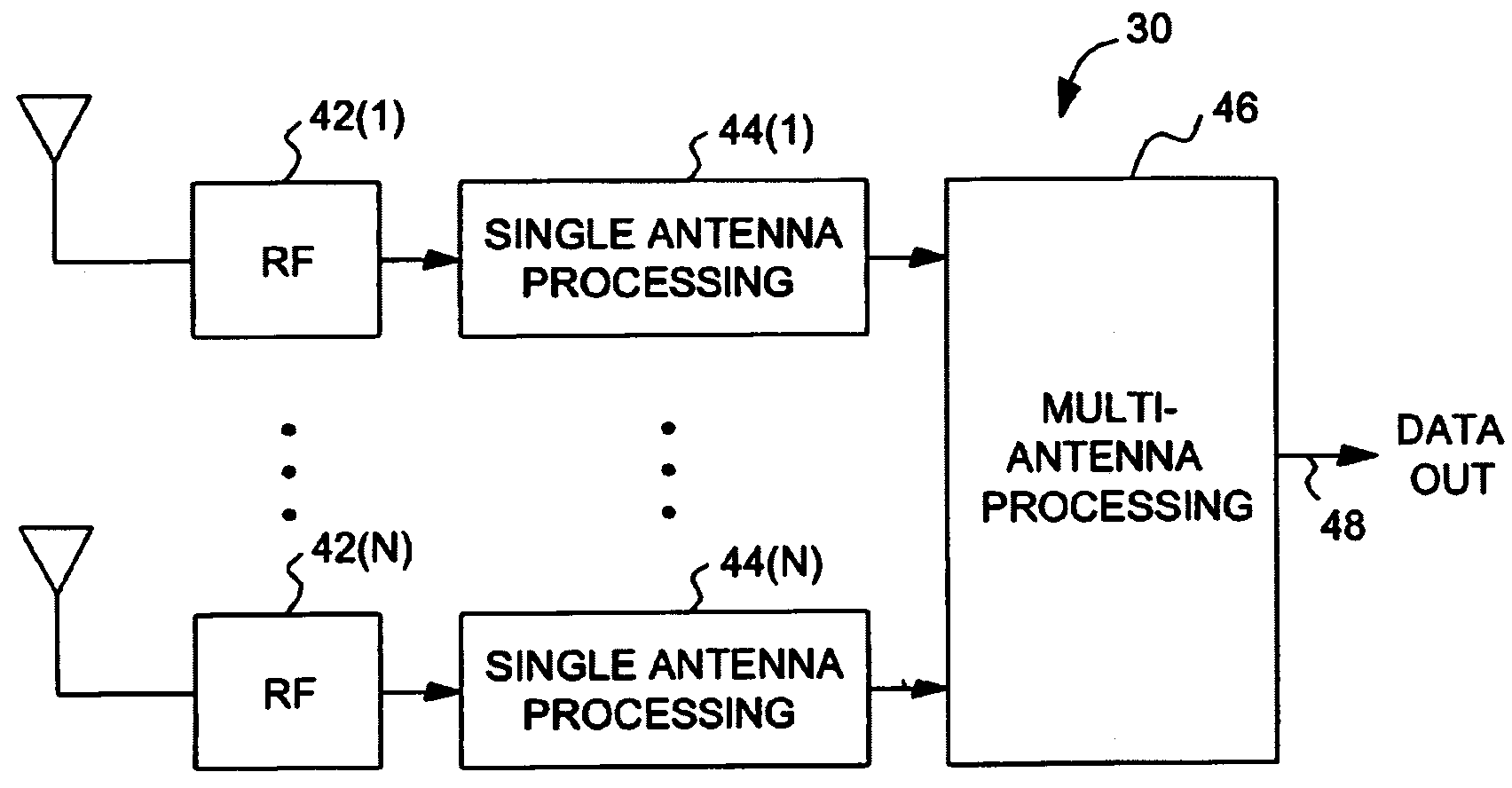
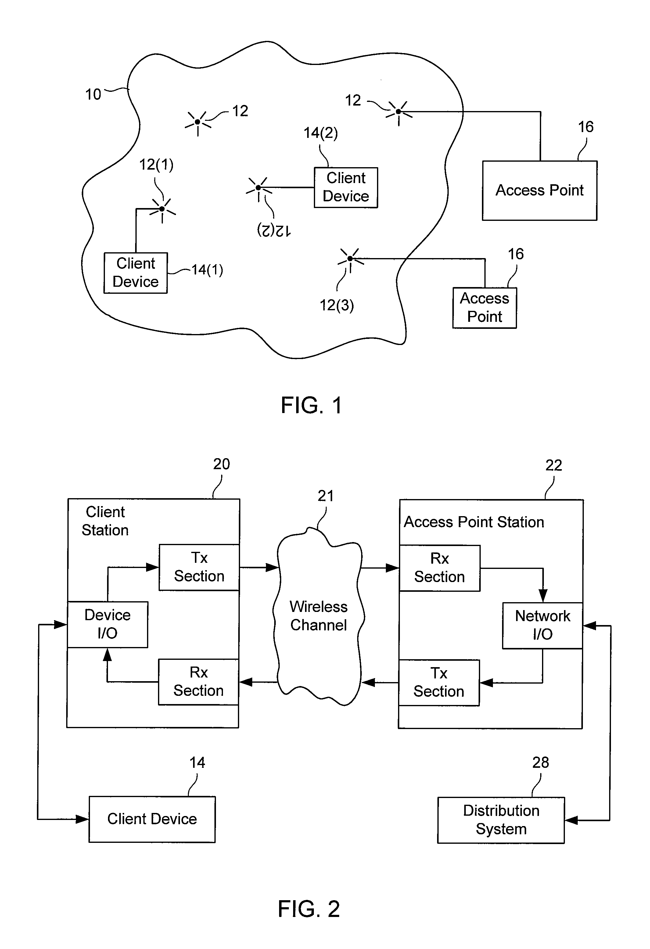
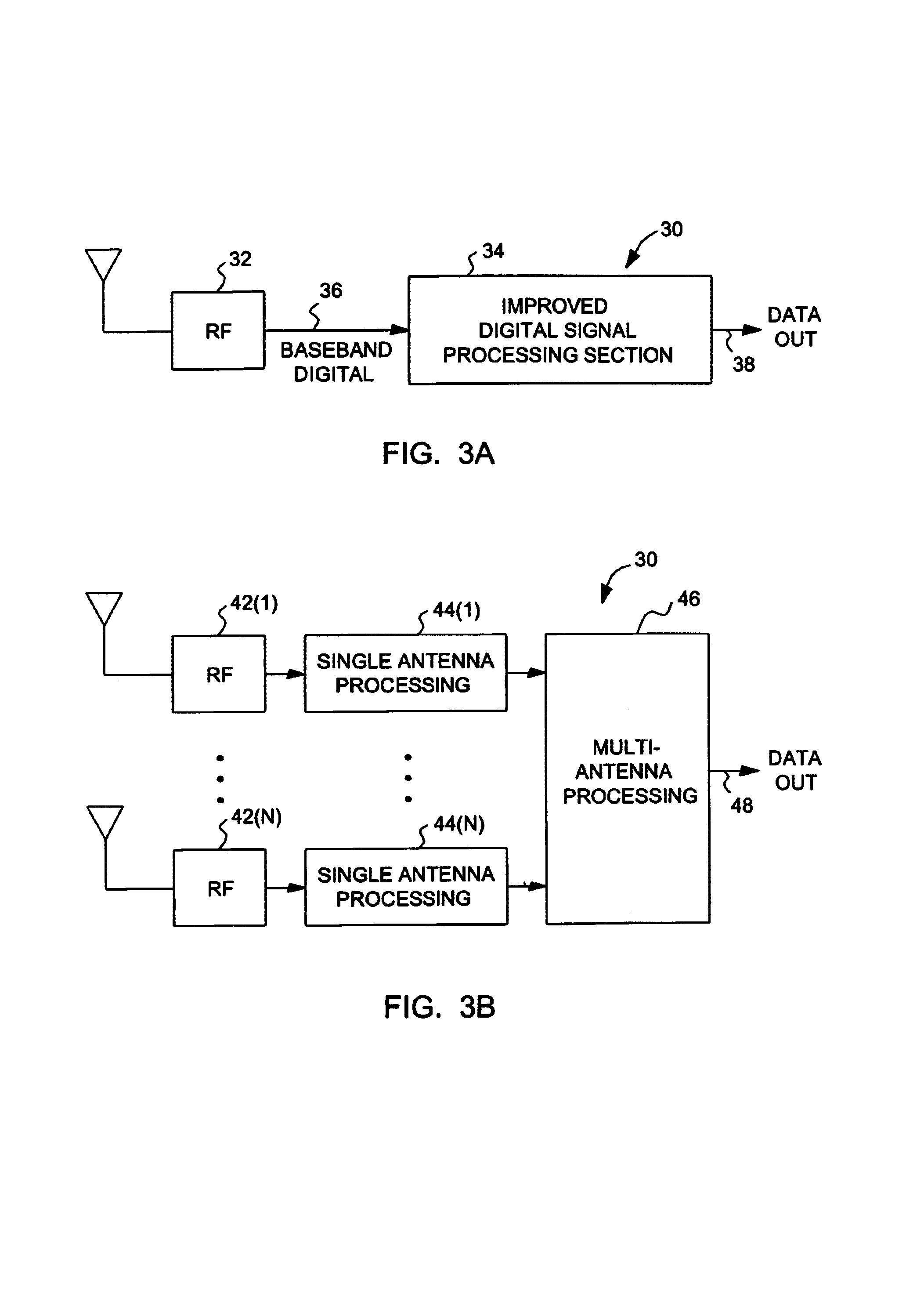
BACKGROUND OF THE INVENTION[0001]Wireless networks have become increasingly popular, as computers and other devices can be coupled for data communications without requiring wired connections between the network nodes. One set of standards for wireless networks is the IEEE 802.11 standards, but other wireless standards or protocols might be used instead. Because wireless networks are expected to operate in unfavorable conditions, such as in the presence of reflections, interference, movement of receivers / transmitters, etc., much effort is needed to correctly transmit and receive data over a wireless channel.[0002]A typical node in a wireless network (referred to in the standards as a “station”) includes a receive chain and a transmit chain. A transmit chain typically includes some digital processing and analog, RF circuitry that causes a signal to be transmitted into the wireless channel. A receive chain typically includes one or more antenna, RF and analog circuitry, and digital pro...

Claims


Application Information

Patent Timeline
Patent Type & Authority Patents(United States)
IPC IPC(8): H04L1/02H04B7/08H04L25/03
CPCH04B1/7093H04B7/0851H04B7/0854H04L25/03267
Inventor STEELE, GREGORYVAN NEE, RICHARD D. J.
Owner QUALCOMM INC
Learn More