Hinge

a technology of hinges and hinges, applied in the field of hinges, can solve the problems of small damping of the closing movement and achieve the effect of reducing the damping of the door or flap movemen

Inactive Publication Date: 2006-10-31
ARTURO SALICE
View PDF22 Cites 48 Cited by
  • Summary
  • Abstract
  • Description
  • Claims
  • Application Information

AI Technical Summary

Benefits of technology

[0018]According to another preferred embodiment it is provided that the hinge is provided with a closing device which overcomes the damping force. This embodiment ensures that the hinge according to the invention always reaches its closed position and for example, a door or flap provided with the hinge according to the invention is completely drawn into its closing position after the damping action has completed.

Problems solved by technology

The known hinges thus have only two intermeshing gear members which can be twisted relative to one another to turn the damping member of the rotation damper, which in the closure region of the hinge can only turn the pinion of the rotation damper through a relatively small angle, which results in a correspondingly small damping of the closure movement of the door or flap carried by the moveable hinge section.

Method used


Image

  • Hinge
  • Hinge
  • Hinge

Examples


Embodiment Construction

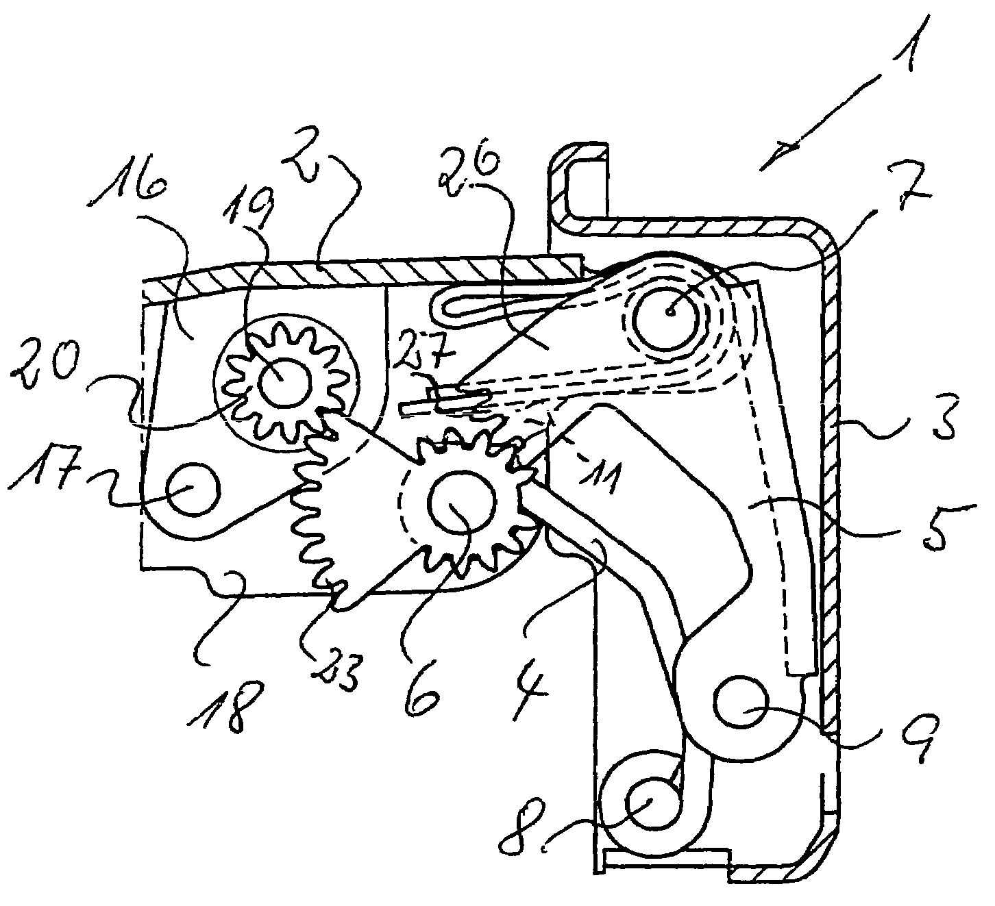
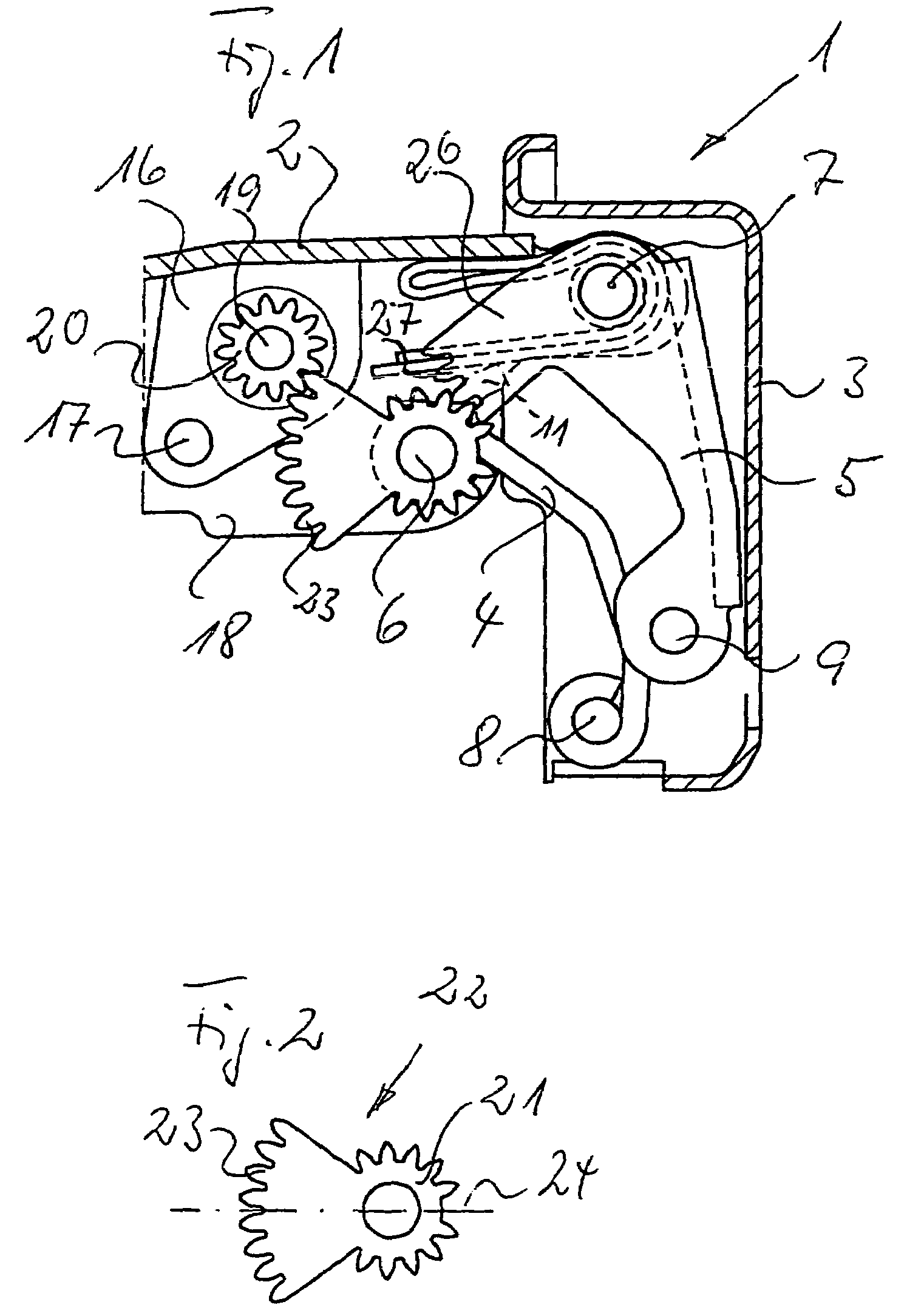
[0027]The hinge according to the invention will be explained below with reference to a four-joint or double-joint hinge.

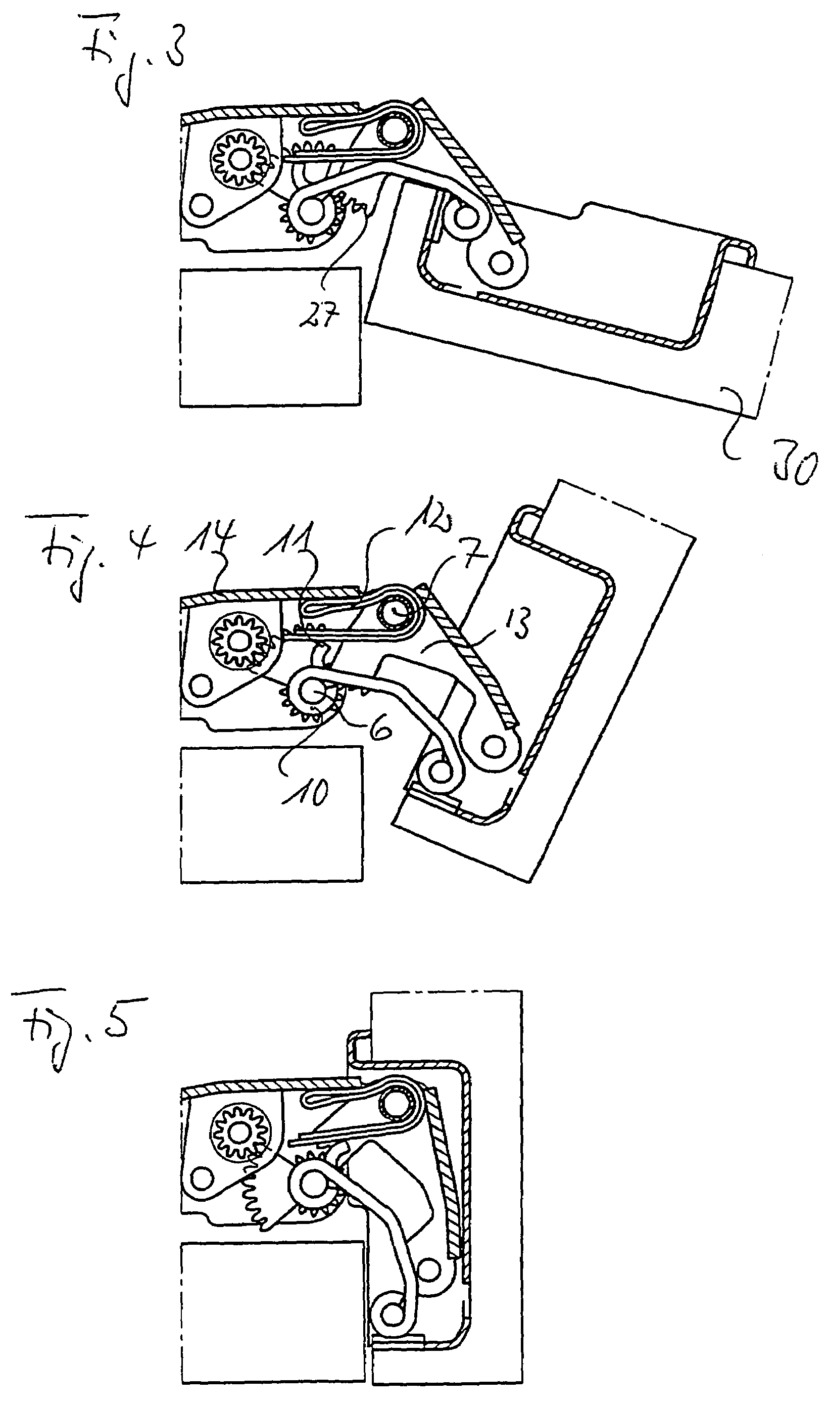
[0028]The double-joint hinge 1 usually consists of a U-shaped hinge arm 2 which can be positioned against a bearing wall and a swivellable cup-shaped hinge section 3 connectable to a door or flap, which is flexibly connected to the hinge section 2 by an inner connecting rod 4 and an outer connecting rod 5 having a U-shaped cross-section. The connecting rods 4, 5 are supported on the one hand on the joint axes of the hinge arm 2 and on the other hand on the joint axes 8, 9 of the cup-shaped hinge section 3 in the usual fashion. Bent out from the inner rolled-up bearing eye 10 of the inner connecting rod 4 is a tongue 11 forming a cam which slides in a fashion which can be seen from FIGS. 3 to 5 on the inner leg of the of the double-layer hairpin-shaped locking spring 12 which is held between the legs 13 of the U-shaped connecting rod 5 on the joint axis 7 and is sup...


PUM


Abstract

The invention relates to a hinge comprising a moveable hinge section and a hinge section consisting of a fixed stop section, which are interconnected by at least one joint axis, and comprising a damping device mounted on one of the hinge sections whose translationally or rotatably moveable damping member is acted upon at least in the closure region of the hinge via gear means from the other hinge section. According to the invention for adjustment of the moveable damping member depending on the tilt of the moveable hinge section relative to the at least one joint axis, there is provided at least three moveable gear members are provided, of which one is the damping member itself.

Description

BACKGROUND OF THE INVENTION[0001]The invention relates to a hinge, preferably for furniture, comprising a moveable hinge section and a hinge section consisting of a fixed stop section, which are interconnected by at least one joint axis, and comprising a damping device mounted on one of the hinge sections whose translationally or rotatably moveable damping member is acted upon at least in the closure region of the hinge via gear means from the other hinge section.[0002]Hinges of this type are known from DE 201 04 100 U1 and DE 202 05 905 U1 wherein the damping devices consist of rotation dampers fixedly connected to a hinge section, whose pinions mesh with tilted toothed segments from the other hinge section. The known hinges thus have only two intermeshing gear members which can be twisted relative to one another to turn the damping member of the rotation damper, which in the closure region of the hinge can only turn the pinion of the rotation damper through a relatively small angl...

Claims


Application Information

Patent Timeline
Patent Type & Authority Patents(United States)
IPC IPC(8): E05D7/00E05F1/08E05D3/06E05D3/18E05D5/08E05D7/086E05D11/10E05F5/02
CPCE05F5/006E05D11/1021E05Y2201/21E05Y2201/254E05Y2201/266E05Y2201/626Y10T16/53833E05Y2201/716E05Y2600/45E05Y2800/21E05Y2900/20Y10T16/5383Y10T16/541E05Y2201/712E05D11/10
Inventor SALICE, LUCIANO
Owner ARTURO SALICE
Why Eureka
Try Eureka