Launch tube system having inflatable bladder shock isolation

a technology of shock isolation and launch tube, which is applied in the direction of torpedo launchers, hulls, vessel construction, etc., can solve the problems of reducing the velocity of the shock isolation material in the launch tube, interfering with or restricting the amount, and projectiles further down in the stack may have trouble clearing all the bonded shock isolation materials in the launch tube without experiencing velocity reduction

Inactive Publication Date: 2006-10-31
NAVY UNITED STATES OF AMERICA THE AS REPRESENTED BY THE DEPT OF THE
View PDF5 Cites 7 Cited by
  • Summary
  • Abstract
  • Description
  • Claims
  • Application Information

AI Technical Summary

Benefits of technology

[0008]In accordance with the present invention, a launch tube system has shock isolation for a projectile housed therein. Two concentric sleeves are utilized with an inner sleeve defining a launch tube and an outer sleeve surrounding the inner sleeve and spaced apart therefrom. The inner sleeve has a plurality of holes formed therethrough. One or

Problems solved by technology

The bonded material remains permanently in the launch tube and often interferes with or restricts the amount of exhaust that can be vented from the launch tube during a launch event.
Also, when launch tube designs re

Method used


Image

  • Launch tube system having inflatable bladder shock isolation
  • Launch tube system having inflatable bladder shock isolation
  • Launch tube system having inflatable bladder shock isolation

Examples


Embodiment Construction

)

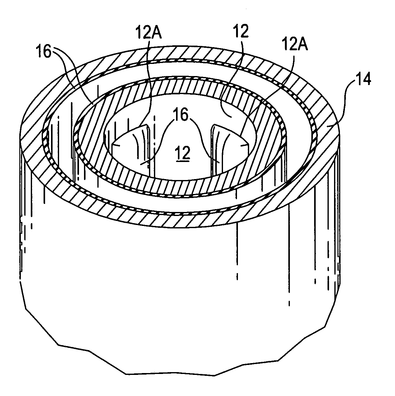
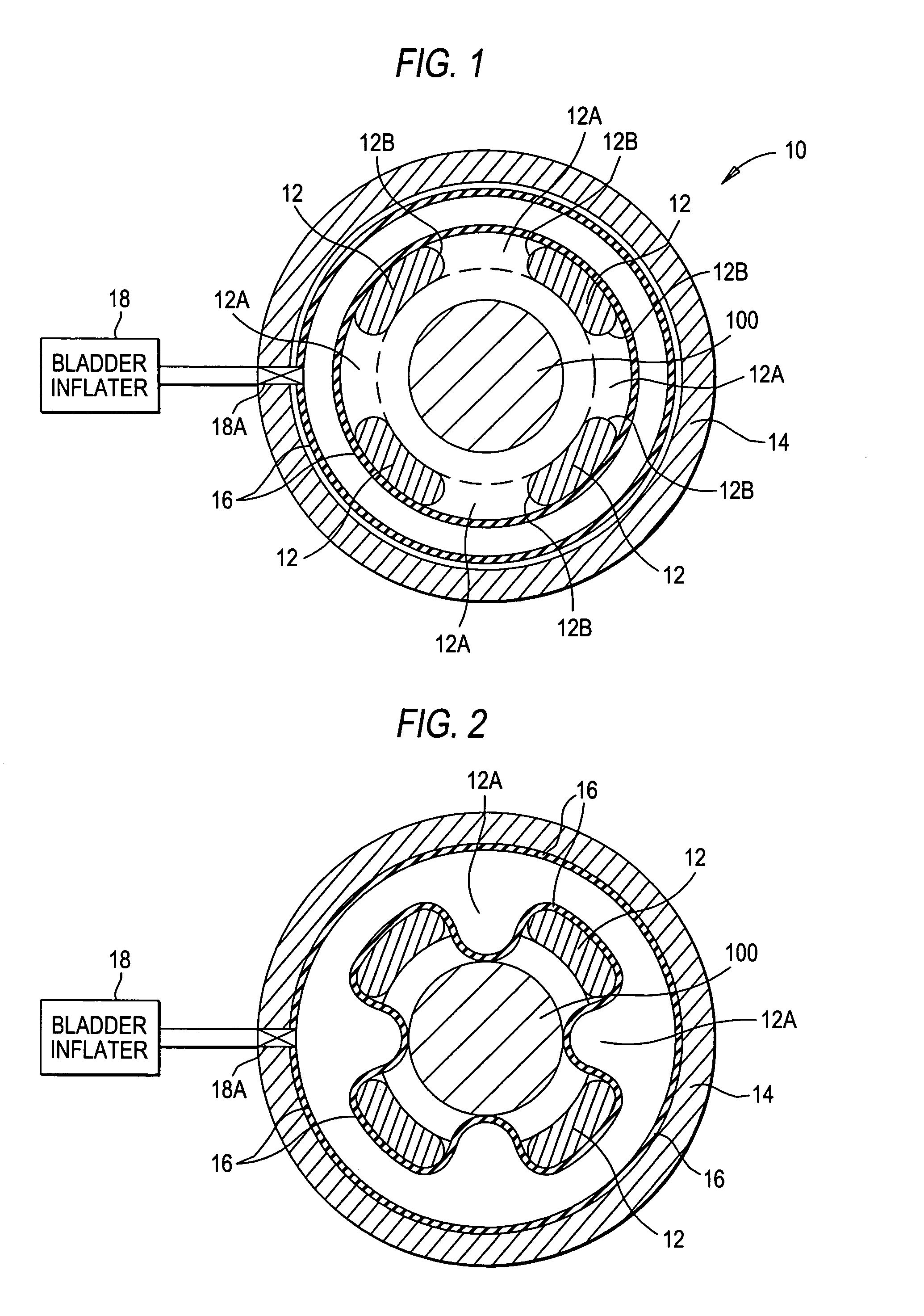
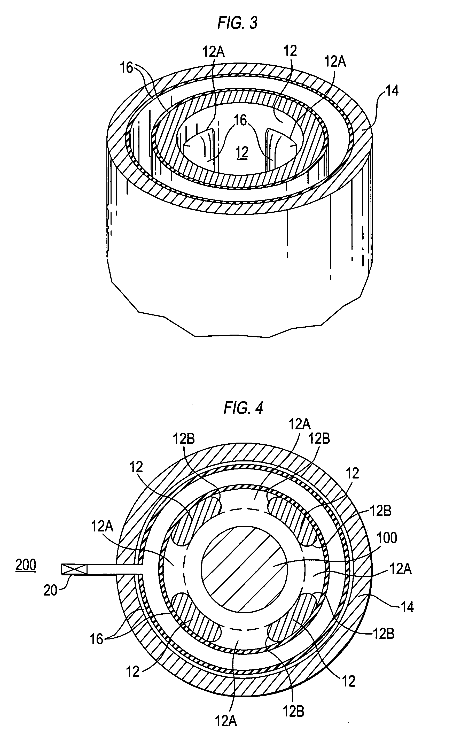
[0014]Referring now to the drawings, and more particularly to FIG. 1, a cross-sectional view of a launch tube system in accordance with the present invention is shown and is referenced generally by numeral 10. Launch tube system 10 houses a projectile 100 prior to and during the launch thereof. The type of projectile 100 is not a limitation of the present invention. Accordingly, projectile 100 can be any size / configuration, and could be weapon or non-weapon based without departing from the scope of the present invention. Further, the type of launch system used to expel projectile 100 from launch tube system 10 is not a limitation of the present invention.

[0015]Launch tube system 10 generally includes an inner tube or sleeve 12, an outer tube or sleeve 14, a sealed bladder 16, and a bladder inflator 18. More specifically, inner sleeve 12 and outer sleeve 14 are concentric sleeves with inner sleeve 12 serving as a launch tube for projectile 100. Typically, sleeves 12 and 14 are made ...


PUM


Abstract

A launch tube system has two concentric sleeves. An inner sleeve having holes formed therethrough defines a launch tube, and an outer sleeve surrounds the inner sleeve and is spaced apart therefrom. One or more flexible bladders are disposed between the inner outer sleeves. When filled with fluid, the flexible bladder(s) expands and extends into and through the holes and into confines of the inner sleeve to thereby form shock isolation for a projectile housed in the inner sleeve.

Description

STATEMENT OF GOVERNMENT INTEREST[0001]The invention described herein may be manufactured and used by or for the Government of the United States of America for governmental purposes without the payment of any royalties thereon or therefor.BACKGROUND OF THE INVENTION[0002](1) Field of the Invention[0003]The present invention relates generally to shock isolation in launch tubes, and more particularly to a launch tube system that uses an inflatable bladder to provide shock isolation.[0004](2) Description of the Prior Art[0005]Underwater shock is a major consideration when designing underwater launch tubes. In the past, elastomeric or polymeric materials have been permanently bonded to the inside surfaces of launch tubes to provide shock isolation around the circumference of a projectile (e.g., weapon, sensor system, etc.) loaded in the launch tube. The bonded material remains permanently in the launch tube and often interferes with or restricts the amount of exhaust that can be vented f...

Claims


Application Information

Patent Timeline
IPC IPC(8): B63B1/00
CPCF41F3/052F41F3/07F41F3/073F41F3/10
Inventor PLUNKETT, STEPHEN J.DOOLEY, RICHARD E.
Owner NAVY UNITED STATES OF AMERICA THE AS REPRESENTED BY THE DEPT OF THE
Why Eureka
Try Eureka