Supercharge Your Innovation With Domain-Expert AI Agents!

Fabric window blind

a fabric window blind and fabric roller blind technology, applied in the direction of curtain suspension devices, door/window protection devices, shutters/movable grilles, etc., can solve the problems of destroying the beauty of the window, the function of the above-mentioned roller blind is still not satisfactory, etc., and achieve the effect of reducing the volume of the head fram

Inactive Publication Date: 2006-10-31
NIEN MADE ENTERPRISE CO LTD
View PDF13 Cites 17 Cited by
  • Summary
  • Abstract
  • Description
  • Claims
  • Application Information

AI Technical Summary

Benefits of technology

The present invention is a fabric window blind that has several technical effects. Firstly, it reduces the volume of the head frame by keeping the shades rolled up. Secondly, it prevents the shade from wrinkling. Thirdly, it allows the user to adjust the tilting angle of the slats at any position. To achieve these objectives, the fabric window blind comprises a head frame, a roller, an adjustment mechanism, slats, a bottom rail and a light-admitting shade. The roller is mounted inside the head frame and the adjustment mechanism has a control axle and two cord member sets with top ends connected to the control axle and bottom ends suspended from it. The slats are arranged at different elevations below the control axle and each has two opposite lateral sides joined to the cord member sets. The bottom rail is fastened to the bottom ends of the cord member sets below the slats and the shade has a first end fastened to the head frame and a second end extended downwardly over the bottom rail and turned upwards toward the head frame and fastened to the roller.

Problems solved by technology

The aforesaid roller blind 1 is still not satisfactory in function.
Installing a bulky head frame in the top side of a window destroy the sense of beauty of the window.

Method used


Image

  • Fabric window blind
  • Fabric window blind
  • Fabric window blind

Examples


Embodiment Construction

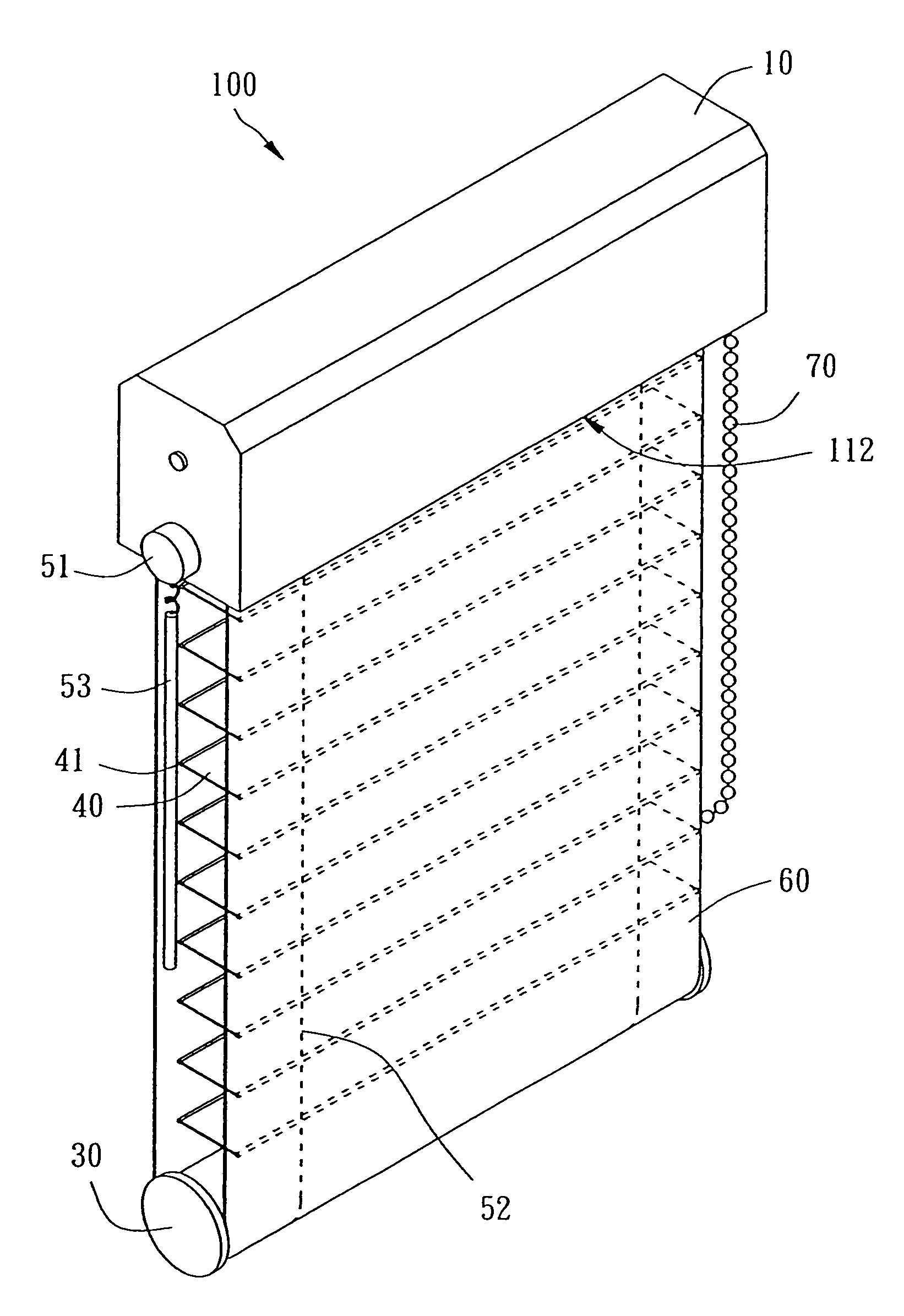
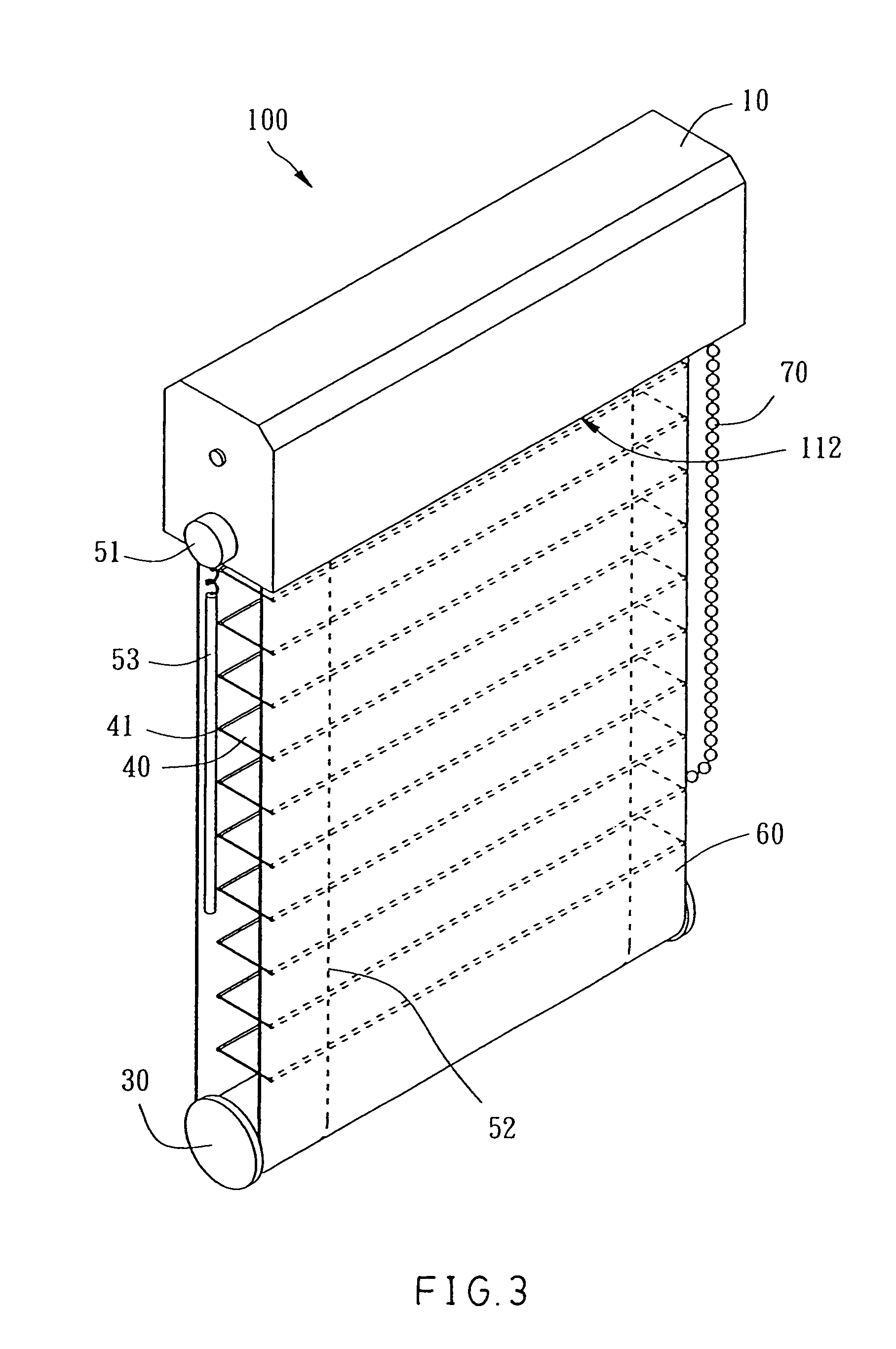
[0021]Referring to FIGS. 3–7, a fabric window blind 100 in accordance with the present invention is shown comprised of a head frame 10, a roller 20, a bottom rail 30, a plurality of slats 40, an adjustment mechanism 50, a shade 60, a lifting mechanism 70, and an antireverse member 80.

[0022]The head frame 10 is a narrow elongated box member affixed to the top side of a window defining a longitudinally extended receiving chamber 111 and a bottom opening 112 in communication with the receiving chamber 111.

[0023]The antireverse member 80, which is a check pawl in this embodiment, is formed of a spring plate suspended inside the receiving chamber 111, having a top end pivoted to the inside wall of the head frame 10 at the top side of the receiving chamber 111 and a bottom end terminating in a retaining tip 81. Because the check pawl 80 is not firmly affixed to the inside wall of the head frame 10, it can be biased upwards or downwards by an external force or forced downwards by the gravi...


PUM


Abstract

A fabric window blind includes a head frame, a roller, an adjustment mechanism, slats, a bottom rail and a light-admitting shade. The roller is horizontally rotatably mounted inside the head frame. The adjustment mechanism has a control axle horizontally pivotally mounted inside the head frame below the roller, and two cord member sets having top ends connected to the control axle and bottom ends vertically downwardly suspended from the control axle. The slats are arranged at different elevations below the control axle. The slats each have two opposite lateral sides respectively joined to the cord member sets. The bottom rail is fastened to the bottom ends of the cord member sets below the slats. The shade has a first end fastened to the head frame, and a second end extended downwardly over the bottom rail and turned upwards toward the head frame and fastened to the roller.

Description

[0001]This Non-provisional application claims priority under 35 U.S.C. § 119(a) on Patent Application No(s). 093203376 filed in Taiwan, Republic of China on Mar. 5, 2004, the entire contents of which are hereby incorporated by reference.BACKGROUND OF THE INVENTION[0002]1. Field of the Invention[0003]The present invention relates to a fabric window blind and more particularly, to a double-layer fabric roller blind.[0004]2. Description of the Related Art[0005]FIGS. 1 and 2 show a conventional roller blind. This structure of roller blind 1 comprises a cylindrical roller 2 horizontally affixed to the top side of a window and rotatable manually or by means of electric driving means, a bottom rail 3 spaced below the roller 2, a plurality of soft slats 4 arranged in parallel at different elevations between the roller 2 and the bottom rail 3, each soft slat 4 having two opposite long sides respectively hemmed with a support rod 5, two cord member sets 6 arranged in parallel near two lateral...

Claims


Application Information

Patent Timeline
Patent Type & Authority Patents(United States)
IPC IPC(8): E06B9/08E06B3/32E06B9/303E06B3/48E06B9/24E06B9/26E06B9/264E06B9/40
CPCE06B9/262E06B9/34E06B2009/2435E06B2009/2627
Inventor NIEN, MING
Owner NIEN MADE ENTERPRISE CO LTD
Features
  • R&D
  • Intellectual Property
  • Life Sciences
  • Materials
  • Tech Scout
  • Unparalleled Data Quality
  • Higher Quality Content
  • 60% Fewer Hallucinations
Learn More