
Transportable storage container assembly

a technology for transportation containers and trailers, applied in the direction of transportation items, loading/unloading vehicle arrangments, mechanical machines/dredgers, etc., can solve the problems of one-person operations using job boxes, individuals cannot employ job boxes at job sites, and inefficient and costly transportation of job boxes to a job si

Inactive Publication Date: 2006-10-31
KRAUSS GERALD W
View PDF35 Cites 20 Cited by
  • Summary
  • Abstract
  • Description
  • Claims
  • Application Information

AI Technical Summary

Benefits of technology

[0006]It is among the principal objects of the invention to provide an apparatus that will allow one individual to conveniently transport and use a construction storage container. The construction storage container and trailer assembly of the present invention allows the tow vehicle's cargo area to remain available for additional construction materials.
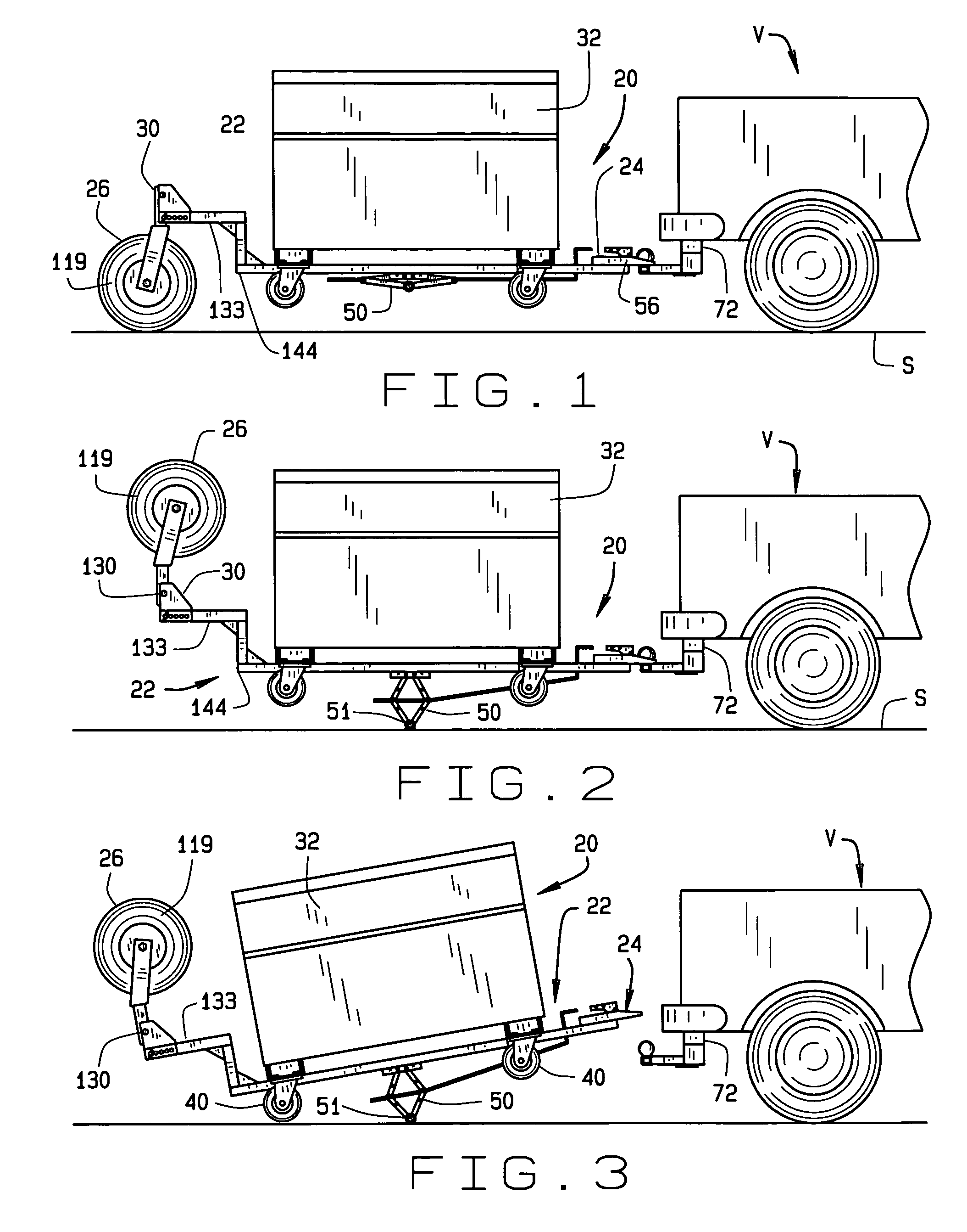
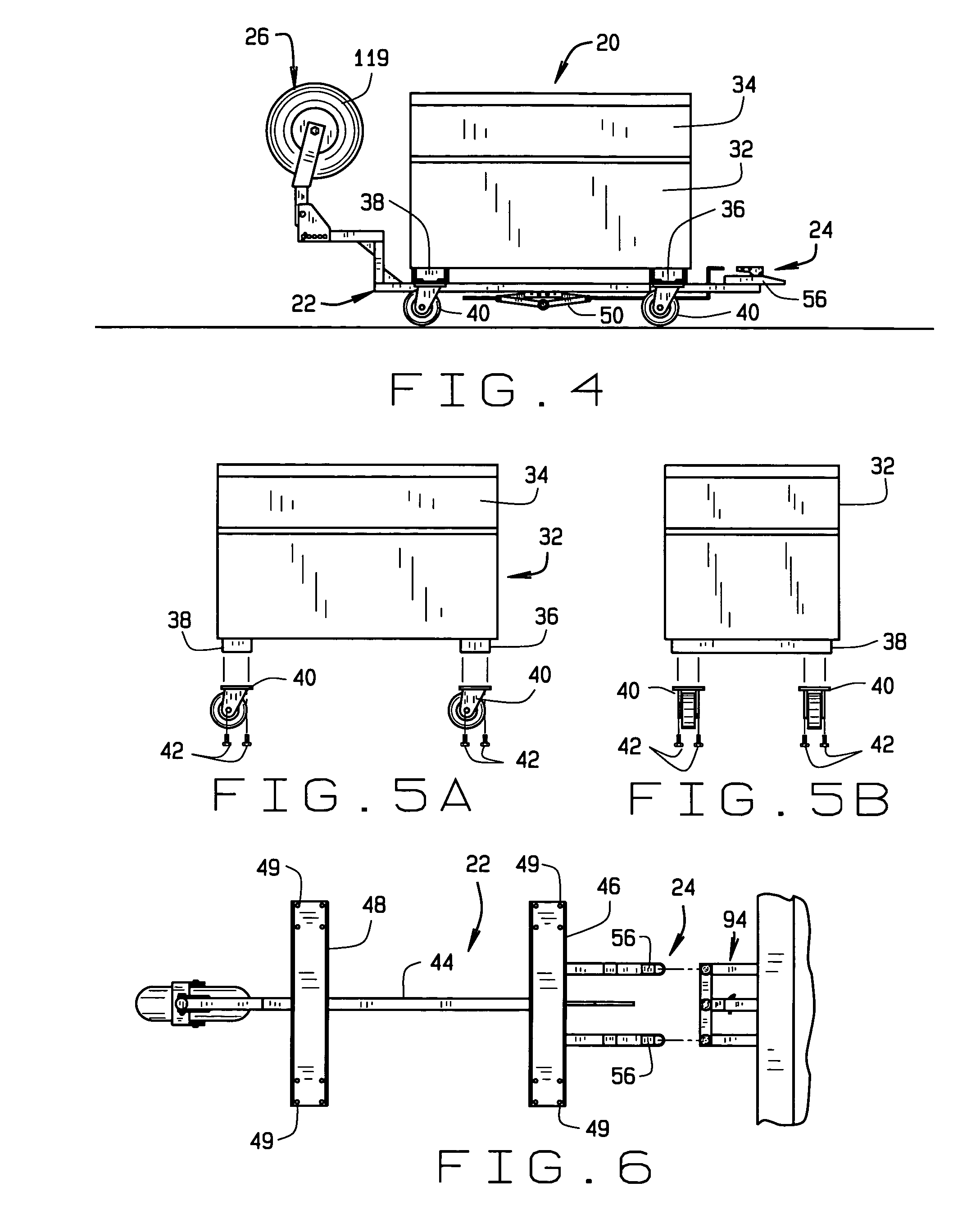
[0007]Briefly stated, a storage box and trailer assembly is provided having a single rail trailer with a pivotable, single wheel design used primarily to haul a conventional construction site storage container. (“Job Box”). The assembly includes a trailer that can be attached to any tow vehicle. The trailer includes a single, central beam or rail. There is a trailer hitch apparatus at the front end of the rail that attaches to the tow vehicle in a two-point attachment configuration so as to prevent tipping of the trailer. There is a single wheel at the rear end of the rail. The single wheel is pivotable to as to be rotated to a down position to engage the road and rotated to an up and out of the way position when the job box is set at a job site. There is a first cross channel adjacent the front end of the rail and a second cross channel adjacent the rear end of the rail. There are holes formed in ends of each cross channel. The cross channels are positioned so that the support skids on the bottom of each end of the job box rest in the respective channels. The job box caster bolts are introduced through the holes in the ends of the channels and secured in the skids to hold the-job box on the trailer. There is a jack on the bottom of the rail to facilitate the raising of the trailer for attachment to and disattachment from the tow vehicle trailer hitch and to raise and lower the rear wheel assembly. In one aspect of the invention, the jack is movable along the rail to allow positioning at various points under the trailer so as to facilitate raising and lower of the assembly.
[0009]The exemplary embodiment of the job box trailer assembly of the present invention utilizing the job box can also be useful for any type of small item delivery, or sample carrying. This same job box trailer assembly can be easily adapted, with the use of attachments, to recreational uses, i.e. to transport luggage, personal belongings, motorcycles, bicycles, camping equipment or the like.
[0011]The job box trailer assembly of the present invention allows transportation of a job box by an individual without extra help. By utilizing the job box trailer assembly of the present invention to transport the job box, the cargo area of the tow vehicle can be reserved for larger construction supplies.

Problems solved by technology

Traditional loading and transportation of a job box to a job site can be an inefficient and costly exercise for contractor or construction company.
A serious problem arises when small independent contractors, tradesmen, or other one-person operations use job boxes.
Such individuals cannot employ a job box at a job site without recruiting temporary help to load and unload the box.
Small companies or individuals are often restricted to using a pickup truck with a camper shell, or a station wagon, loaded down with all the tools and extra supplies needed for the job.

Method used


Image

  • Transportable storage container assembly
  • Transportable storage container assembly
  • Transportable storage container assembly

Examples


Embodiment Construction

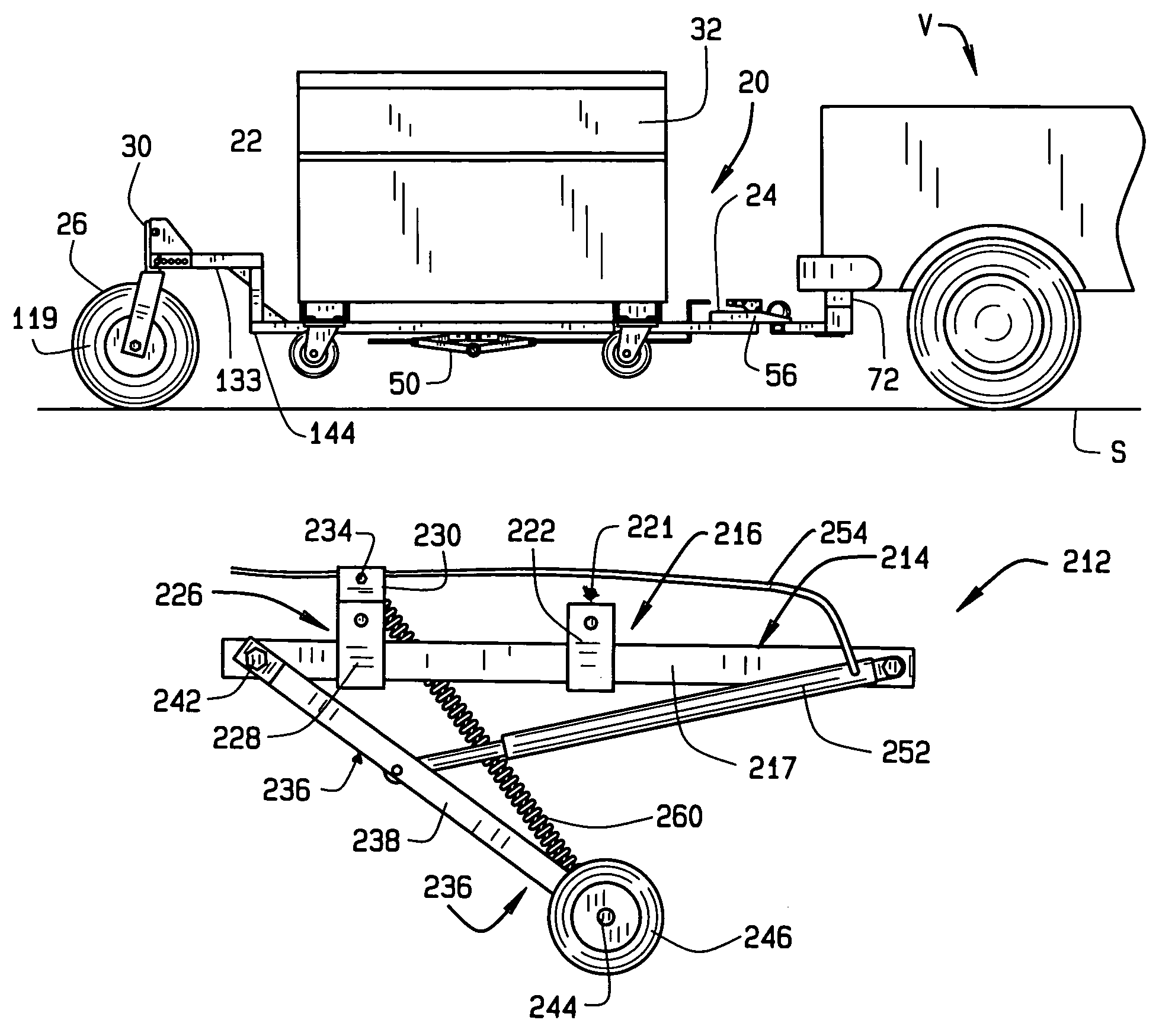
[0036]Referring now to the figures, FIGS. 1 through 3 illustrate one preferred embodiment of the job box trailer assembly of the present invention, indicated generally by reference numeral 20, attached to the rear of a tow vehicle V for transport. As can be seen, the assembly includes a single wheeled trailer 22 having a trailer hitch assembly 24 at the front end for attachment to the tow vehicle V and a single wheel assembly 26 at the other end of the trailer. Wheel 26 is attached to the trailer body itself by a pivot apparatus 30 so that wheel 26 can be rotated or pivoted down into a road-engaging position, as seen in FIG. 1 or up, as shown in FIG. 2. More than one wheel can be employed on the trailer if it includes means for pivoting the wheels up when the assembly is resting on the ground, in use.

[0037]A job box 32 is secured to the trailer, as now will be explained. The job box 32, as seen in greater detail in FIGS. 5A and 5B, can be a conventional, rugged equipment storage box...


PUM


Abstract

A transportable storage container assembly for transport by a tow vehicle. The assembly includes a trailer having a center rail with a two-point trailer hitch at the front end and a pivotable single wheel at the rear end. The trailer has a first cross channel adjacent the front end of the rail and a second cross channel adjacent the rear end of the rail. A storage container mounted on the trailer includes bottom support skids at each end that seat in the cross channels and are secured in the channels by casters that are attached to the skids through mounting holes in the cross channels. There is a jack on the bottom of the trailer rail movable along the length of the rail to facilitate the raising of the trailer for attachment to, and disattachment from, the tow vehicle trailer hitch.

Description

CROSS-REFERENCE TO RELATED APPLICATIONS[0001]This application is a continuation-in-part of application Ser. No. 10 / 151,401, filed May 20, 2002, now U.S. Pat. No. 6,755,433, which claims priority to provisional application Ser. No. 60 / 294,458, filed May 30, 2001.BACKGROUND OF THE INVENTION[0002]The invention relates generally to construction equipment and more specifically an improved storage container and trailer assembly that allows a single user to transport a storage container back and forth to a work site easily and efficiently.[0003]A construction industry storage container is commonly referred to as a “job box”. Job boxes can be purchased from various construction supply companies and some retail outlets. Most job boxes fall within a general size range and employ a substantially uniform design and construction. Job boxes are used by contractors and sub-contractors for the purpose of carrying tools and construction supplies to a job site. The job box usually remains at the site...

Claims


Application Information

Patent Timeline
Patent Type & Authority Patents(United States)
IPC IPC(8): B60D1/50B60D1/06B60D1/66B62D63/06
CPCB60D1/065B60D1/07B60D1/173B60D1/66B62D63/061B62D63/067
Inventor KRAUSS, GERALD W.
Owner KRAUSS GERALD W
Learn More