Surface light-emitting device

a surface light and light-emitting technology, which is applied in the direction of lighting and heating apparatus, instruments, mechanical equipment, etc., can solve the problems of ineffective light-emitting means disposed uniformly along the light-emitting surface, limited light-unifying means, and inability to increase the uniformity of brightness

Inactive Publication Date: 2006-10-31
3M INNOVATIVE PROPERTIES CO
View PDF19 Cites 8 Cited by
  • Summary
  • Abstract
  • Description
  • Claims
  • Application Information

AI Technical Summary

Problems solved by technology

Applications of the surface light-emitting devices capable of emitting light uniformly by using the light source disposed outside of the body (edge lighting light source) and the light unifying means are limited to small light-emitting devices (backlight of a liquid crystal display for personal computers, for example).
Specifically, since the area of the light-emitting surface is comparatively small (generally 80×80 cm or less), these surface light-emitting devices are unsuitable for use as comparatively large displays or planar illumination devices disposed on the indoor plane of the building and the like by forming a light-transmitting plate having a large area by horizontally arranging a plurality of light-transmitting plates, and emitting light from the surface of the large light-transmitting plate.
In the case where the area of the light-emitting surface is increased, in particular, in the case where the length of the light-emitting surface of the surface light-emitting device is greater than the width (the length of the light guiding space is greater than the width), the light unifying means disposed uniformly along the light-emitting surface is not effective for increasing the uniformity of brightness.
However, this results in a decrease in light transmittance of the diffuse transmission film, whereby the brightness of the light-emitting surface is decreased.
However, this results in an increase in the space occupied by the entire surface light-emitting device.
Moreover, since the power consumption is increased by increasing the luminous brightness of the light source or the number of light sources in order to prevent a decrease in brightness, these measures are unfavorable from the viewpoint of energy saving and the like.
Since a large amount of electric power is needed to emit light brightly from such a light source, the power consumption tends to increase.

Method used


Image

  • Surface light-emitting device
  • Surface light-emitting device
  • Surface light-emitting device

Examples


examples

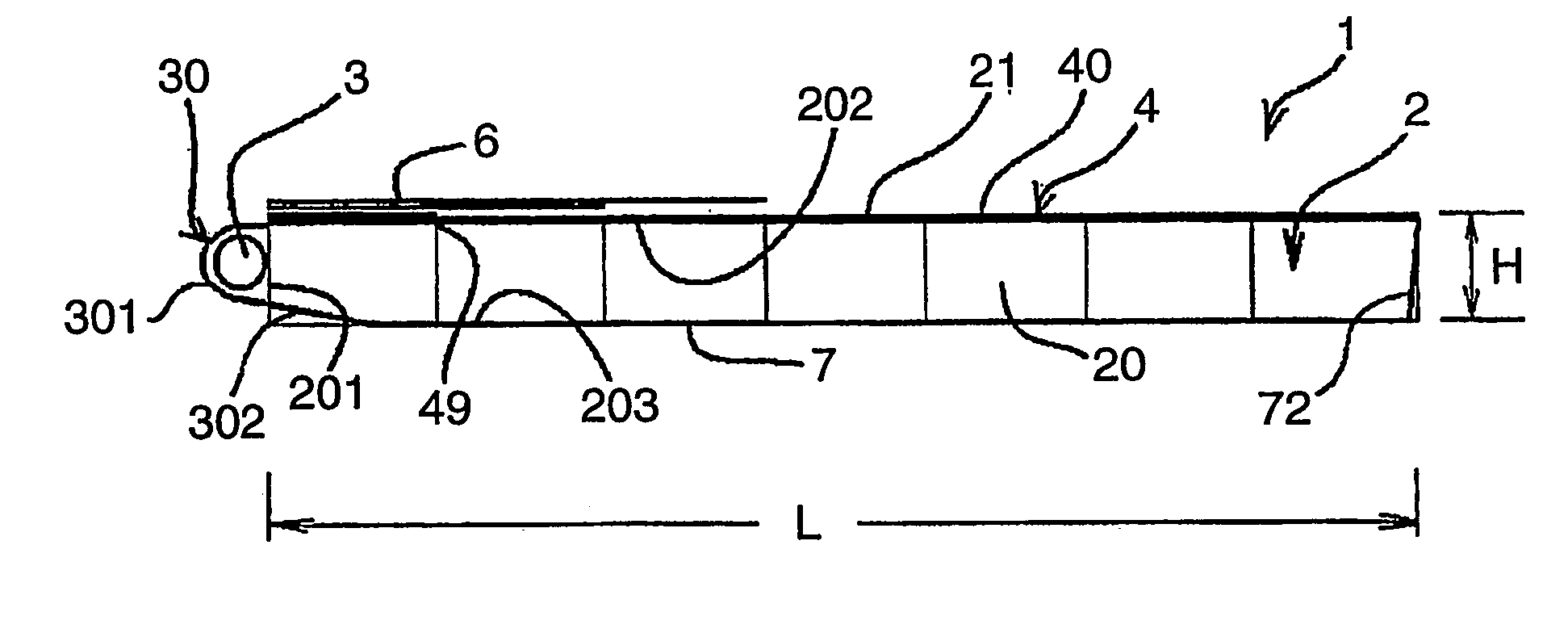
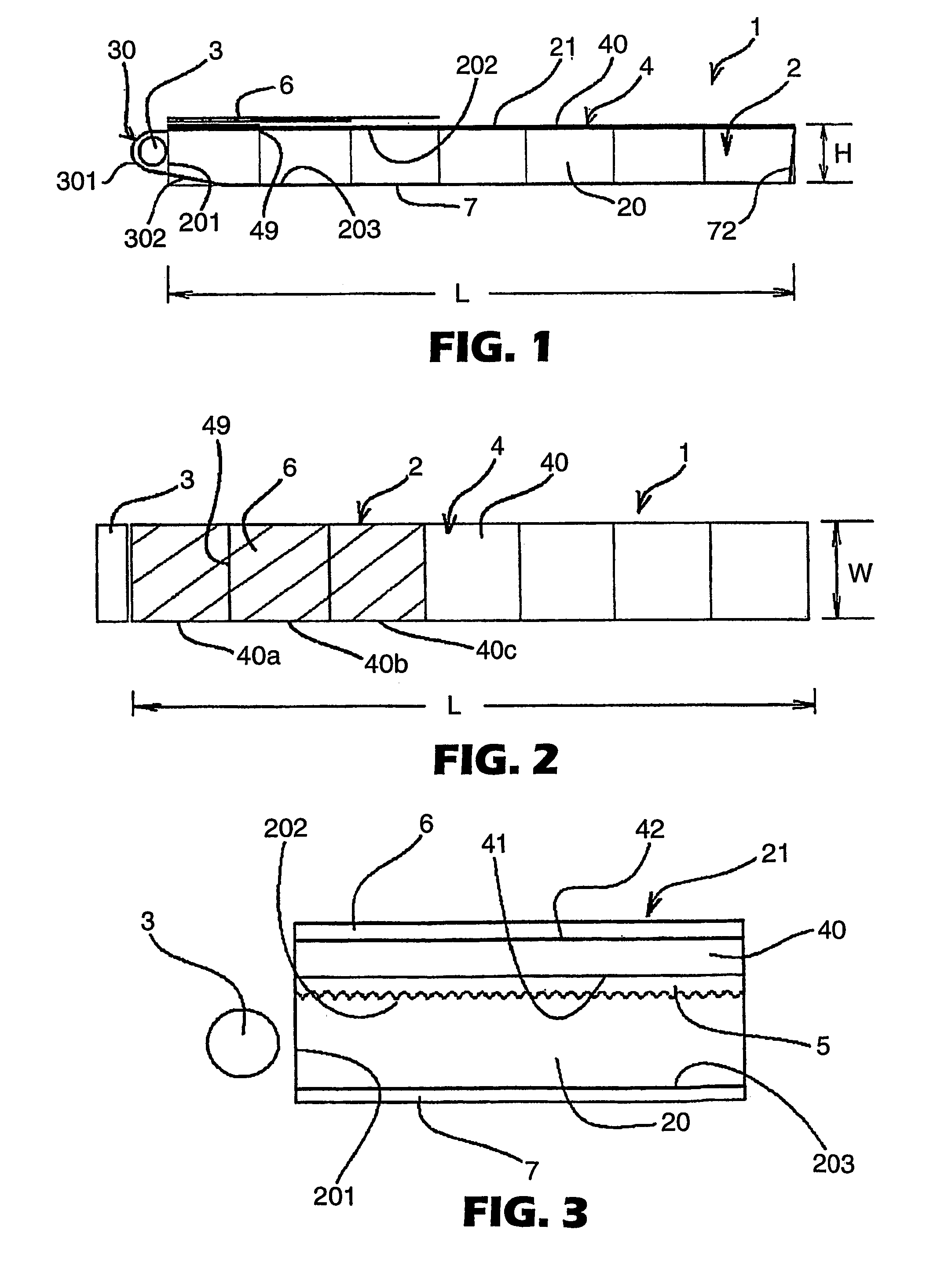
[0075]A surface light-emitting device having a structure shown in FIGS. 1 and 2 was formed. The surface light-emitting device was disposed on the surface of the floor and caused to emit light. A body was provided with a light-transmitting plate formed by arranging seven pieces of block light-transmitting members including a block light-transmitting plate having a planar area of 800×800 mm as shown in the figure. The distance from the surface of the light-transmitting plate to the installation surface (bottom of the light guiding space) was 500 mm. Therefore, the device of this example had a light-emitting surface with an area of 800 mm×5.6 m.

[0076]The body was formed by using a framework of the body formed using frame members made of a metal shown in FIG. 6. The light-transmitting plate was formed of a plurality of block light-transmitting plates. The block light-transmitting plate was formed of reinforced glass having a thickness of 10 mm. The above commercially available prism she...


PUM


Abstract

There is provided a surface light-emitting device capable of preventing an increase in power consumption even if the length of the light-emitting surface of the surface light-emitting device is greater than the width, and capable of emitting light uniformly without decreasing the brightness of the light-emitting surface nor increasing the height of the light guiding space. In the present surface light-emitting device, the incident plane (201) is one of two sides of the light guiding space (20) in opposition in the longitudinal direction. The light-transmitting plate (4) includes a diffusion filter (6) which covers a specific area of the surface of the light-transmitting plate (4) near the light source (3). The remaining area of the surface of the light-transmitting plate at a distance from the light source (3) is not covered with the diffusion filter (6). The diffusion filter (6) is formed of a laminate in which a plurality of diffuse transmission films are layered. The number of diffuse transmission film (6) layers is highest in the area closest to the light source (3) so that the light transmittance is increased as the distance from the light source (3) increases due to a decrease in the diffusion of light, and the number is gradually decreased as the distance from the light source (3) increases.

Description

FIELD OF THE INVENTION[0001]The present invention relates to a surface light-emitting device suitable for use in applications such as traffic signs, comparatively large back-lit type displays for displaying advertisements and the like, and planar illumination devices disposed on an indoor plane or outdoor plane of a building such as the ceiling, floor, and walls.BACKGROUND OF THE INVENTION[0002]Devices called surface light-emitting devices or sheet-type luminous bodies can emit light uniformly from the entire area of the light-emitting surface. Such devices are disclosed in the Published Japanese translation of PCT International Patent Application No. 10-506725, Japanese Patent Applications Laid-open No. 5-224020, No. 7-5326, No. 7-182908, No. 6-265892, No. 1-45003, No. 1-45002, No. 11-154406, No. 4-101639, and the like.[0003]The sheet-type luminous bodies disclosed in these publications generally have the following structure. Specifically, these sheet-type luminous bodies include (...

Claims


Application Information

Patent Timeline
Patent Type & Authority Patents(United States)
IPC IPC(8): F21V8/00
CPCG02B6/0096G02B6/0048G02B6/0051G02B6/0055G02B6/0065
Inventor HASHIMOTO, KAZUYUKI
Owner 3M INNOVATIVE PROPERTIES CO
Why Eureka
Try Eureka