

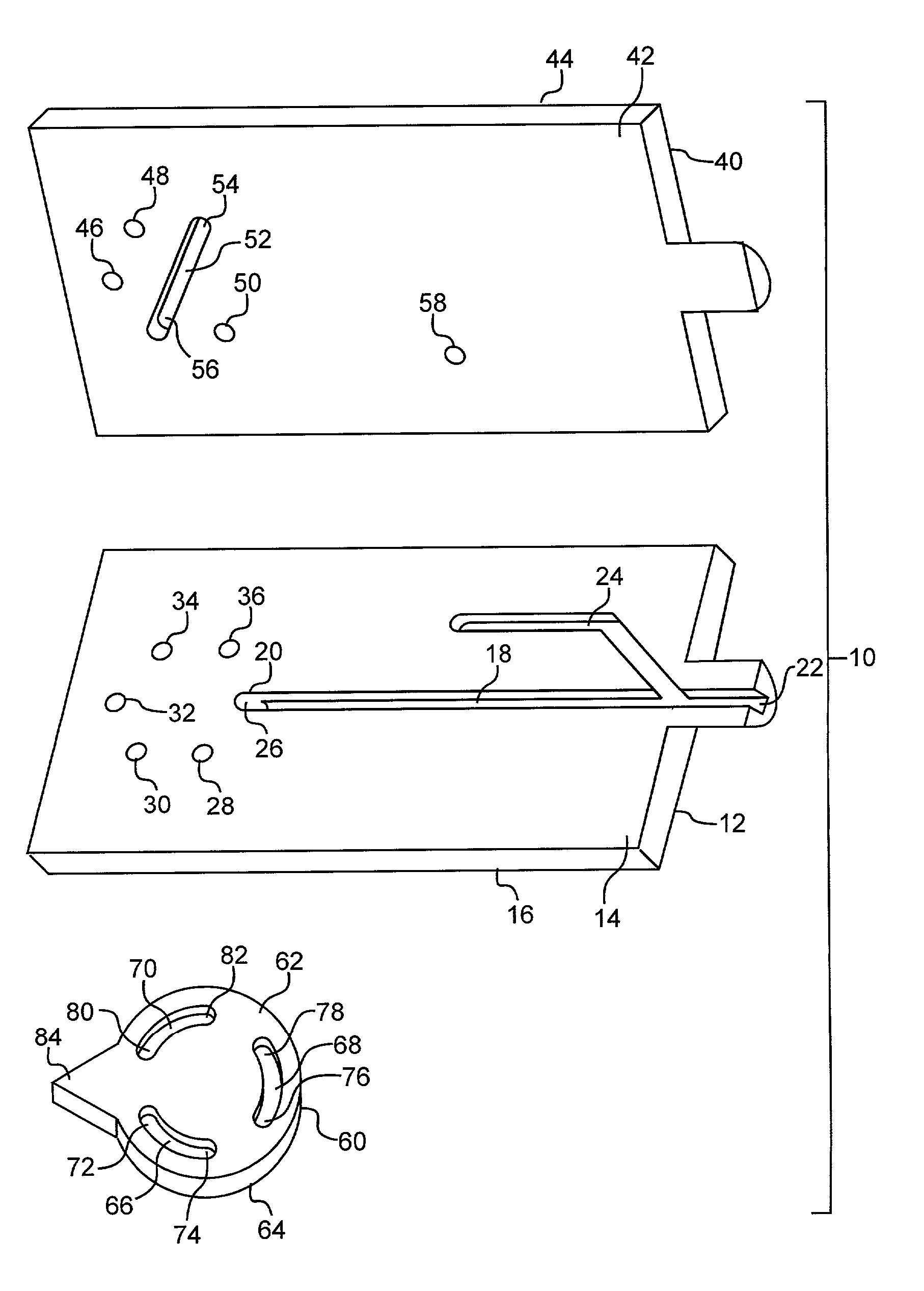
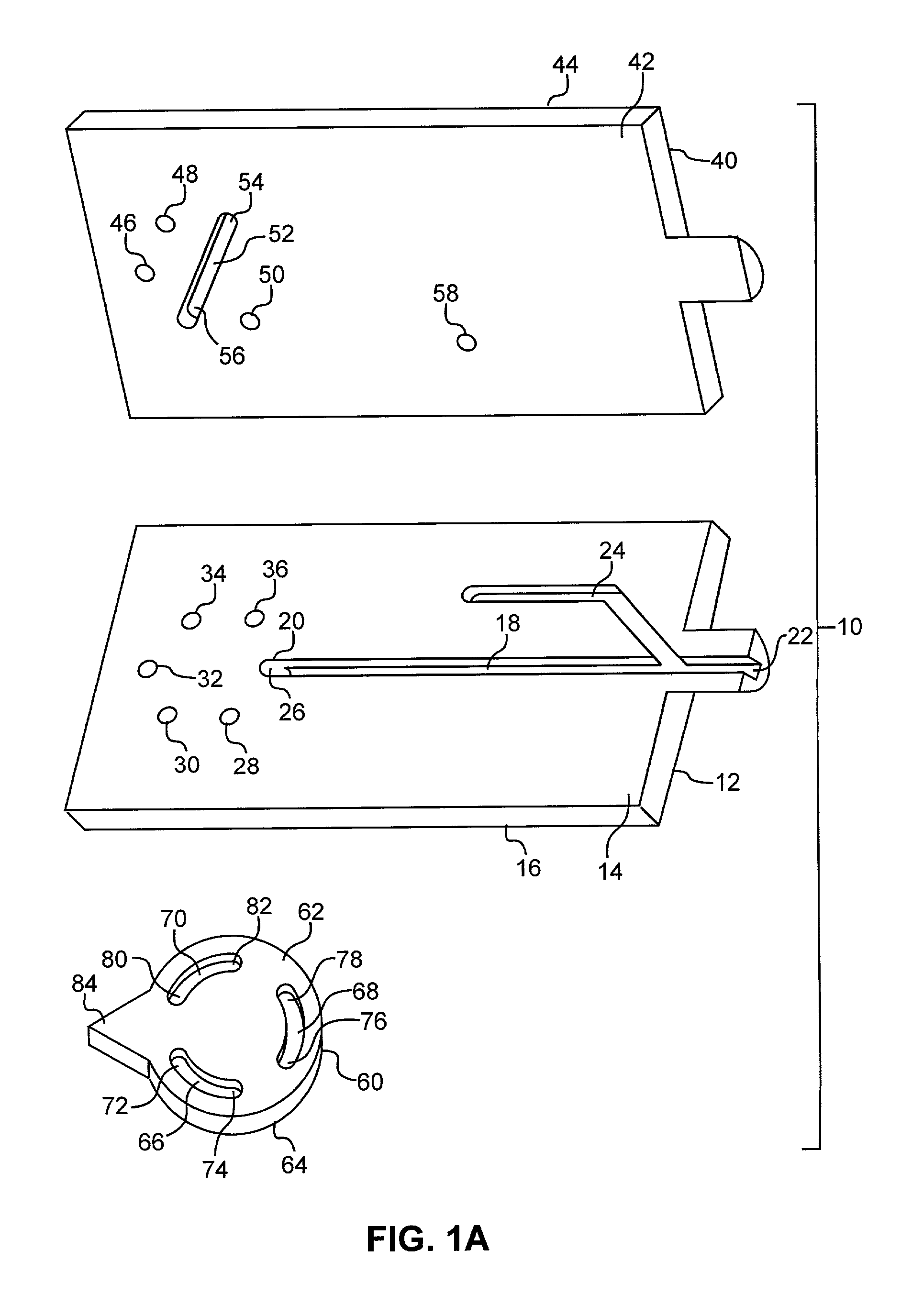
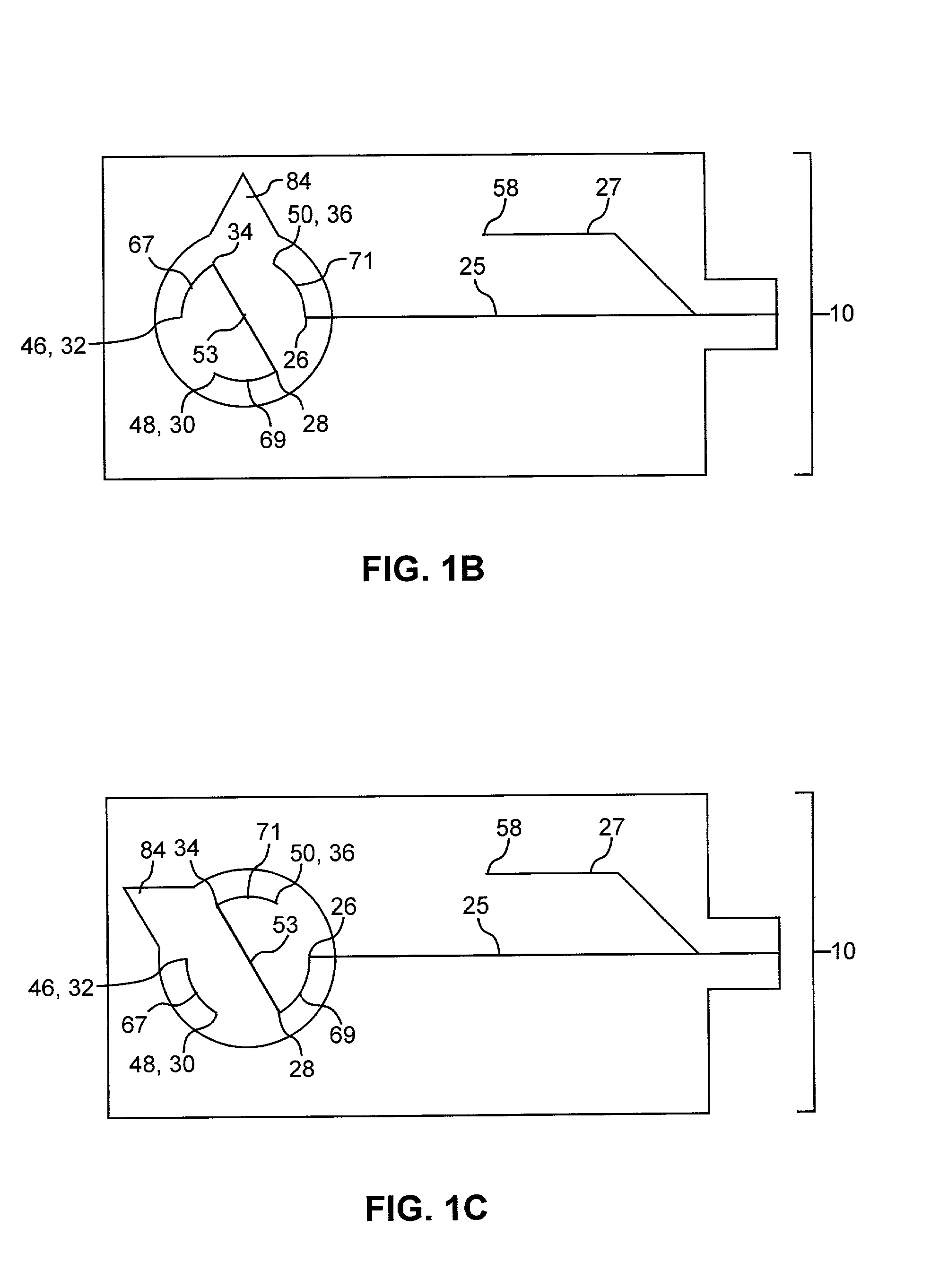
Microdevice and method for component separation in a fluid
a micro-device and component technology, applied in the direction of electrolysis, chemical vapor deposition coating, multiple way valve, etc., can solve the problems of individual control of flow switching and separation in capillary electrochromatography, interfering moieties such as salts are washed away, and the capillary electrophoresis is not compatible with chromatographic techniques,
- Summary
- Abstract
- Description
- Claims
- Application Information
AI Technical Summary
Benefits of technology
Problems solved by technology
Method used
Image

Examples
Embodiment Construction
[0022]Before the invention is described in detail, it is to be understood that unless otherwise indicated this invention is not limited to particular materials, components or manufacturing processes, as such may vary. It is also to be understood that the terminology used herein is for purposes of describing particular embodiments only, and is not intended to be limiting.
[0023]It must be noted that, as used in the specification and the appended claims, the singular forms “a,”“an” and “the” include plural referents unless the context clearly dictates otherwise. Thus, for example, reference to “a microchannel” includes a plurality of microchannels, reference to “a fluid” includes a mixture of fluids, reference to “a component property” includes a plurality of component properties and the like.
[0024]In this specification and in the claims that follow, reference will be made to a number of terms that shall be defined to have the following meanings:
[0025]The term “constructed” as used her...
PUM
| Property | Measurement | Unit |
|---|---|---|
| diameter | aaaaa | aaaaa |
| length | aaaaa | aaaaa |
| diameter | aaaaa | aaaaa |
Abstract
Description
Claims
Application Information