Fuse box

a fuse box and watertight technology, applied in the field of fuse boxes, can solve the problems of water not passing through the slight gap the inability of the second watertight portion to pass through the second watertight portion, etc., to achieve the effect of reliable waterproof function, improved fuse box layout, and improved waterproof function

Inactive Publication Date: 2006-10-31
SUMITOMO WIRING SYST LTD
View PDF17 Cites 10 Cited by
  • Summary
  • Abstract
  • Description
  • Claims
  • Application Information

AI Technical Summary

Benefits of technology

[0007]A lower end surface of a peripheral wall of the upper cover is brought into contact with a bottom wall of a lower cover that is locked to the case body of the fuse box or brought into contact with a bottom wall of the case body to form a first watertight portion. A peripheral wall erect on the bottom wall of the case body is formed by spacing the peripheral wall at a pressure-reducing gap from an inner surface of the upper cover. An upper end of the peripheral wall of the case body is bent and projected toward an inner surface of the peripheral wall of the upper cover to form a second watertight portion. The pressure-reducing gap is interposed between the first watertight portion and the second watertight portion. The pressure-reducing gap reduces a high pressure of water which has penetrated into the fuse box from the outside through the first watertight portion, thus making it impossible for the water to pass through the second watertight portion disposed above the first watertight portion.
[0008]The above-described waterproof mechanism is constructed by using Bernoulli's theorem and the law of conservation of mass. That is, when water penetrates into the upper cover at a high pressure from a slight gap of the first watertight portion, the water is moved in a right-to-left direction in the pressure-reducing gap interposed between the first watertight portion and the second watertight portion. As a result, the pressure of the water disperses and decreases. Owing to the shortage of the pressure, the water is incapable of passing through the slight gap of the second watertight portion. Thereby it is possible to prevent the water from penetrating into the case body 11. The waterproof mechanism provides stable, constant, and high waterproof performance, thereby preventing the fuse from being exposed to water and corroded.
[0010]That is, it is desirable to form the waterproof mechanism on the entire periphery of the fuse box in terms of waterproof performance. Water which has penetrated to other portions of the fuse box is exhausted from drain holes formed on a lower portion of the fuse box. Therefore the waterproof mechanism may be provided in only a portion on the periphery of the fuse-disposed position which is required to be unexposed to water. The space for the pressure-reducing gap when the waterproof mechanism is provided on a part of the entire periphery is smaller than the space for the pressure-reducing gap when the waterproof mechanism is provided on the entire periphery. Thereby it is possible to improve the layout of the fuse box and make the fuse box compact.
[0011]As is apparent from the foregoing description, according to the present invention, the pressure-reducing gap disperses water which has penetrated into the fuse box at a high pressure from the first watertight portion and reduces the pressure, thus preventing the water from penetrating into the case body from the second watertight portion. Further, even when the peripheral wall of the upper case, the case body or the lower cover warps or shrinks, the watertight performance provided by the waterproof mechanism is not affected adversely. Thus the waterproof mechanism has reliable waterproof function.
[0012]Further by forming the waterproof mechanism in only a portion on the periphery of the fuse-disposed position, it is possible to prevent the fuse from being exposed to water, improve the layout of the fuse box, and make the fuse box compact in a favorable balance.

Problems solved by technology

The pressure-reducing gap reduces a high pressure of water which has penetrated into the fuse box from the outside through the first watertight portion, thus making it impossible for the water to pass through the second watertight portion disposed above the first watertight portion.
Owing to the shortage of the pressure, the water is incapable of passing through the slight gap of the second watertight portion.

Method used


Image

  • Fuse box
  • Fuse box
  • Fuse box

Examples


first embodiment

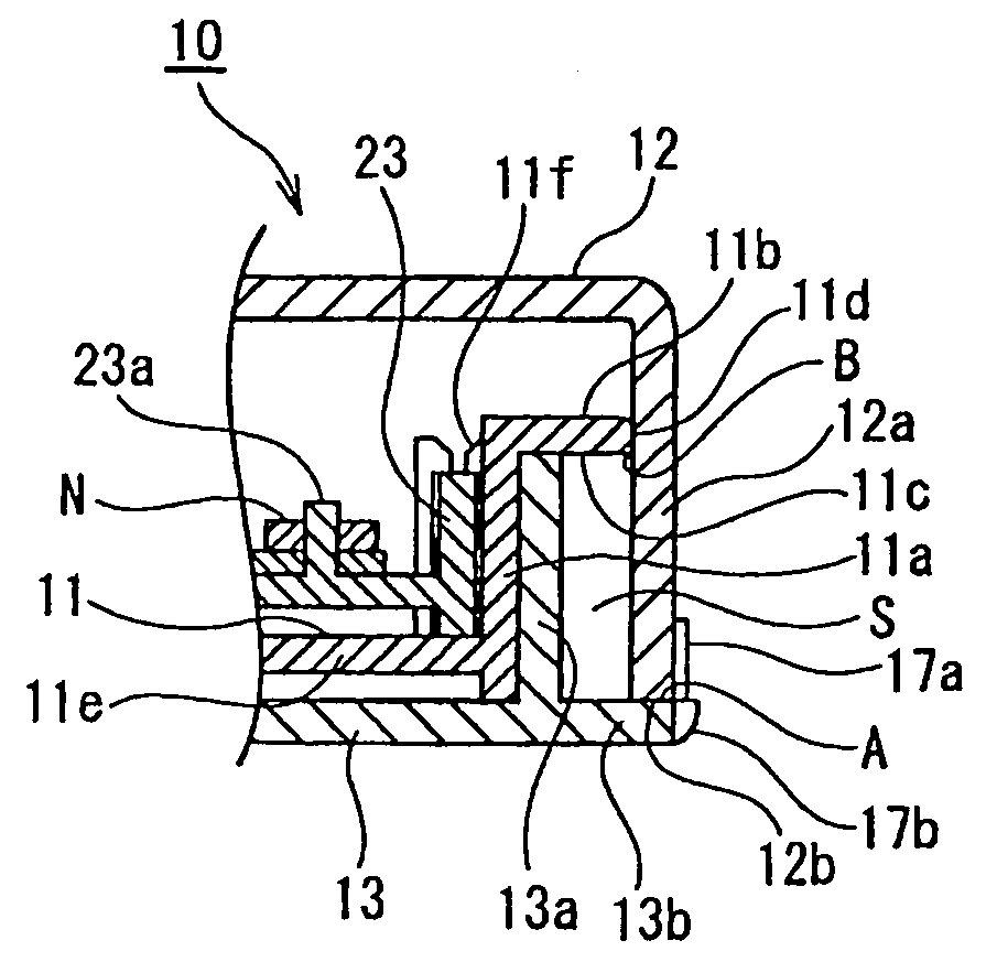
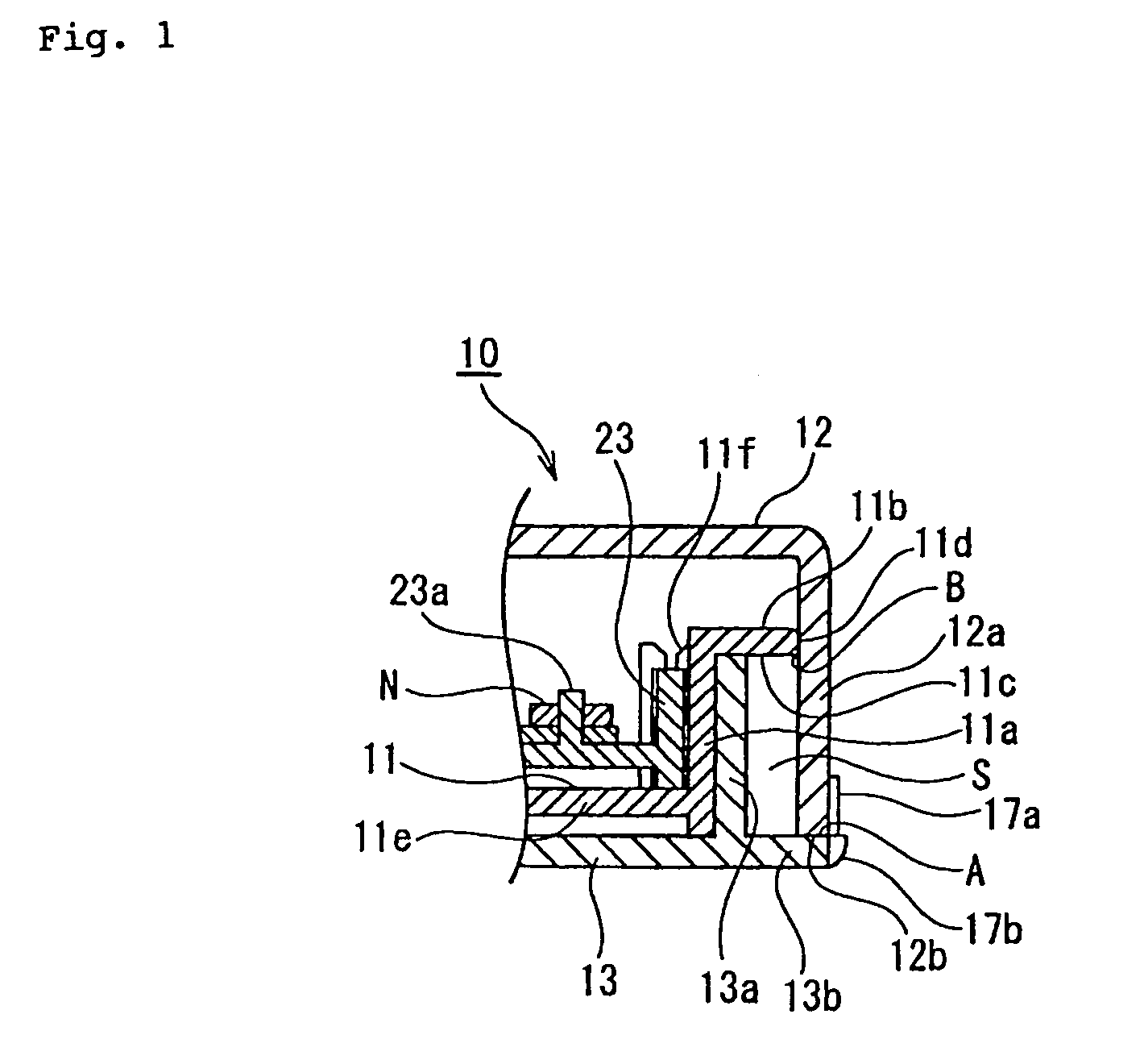
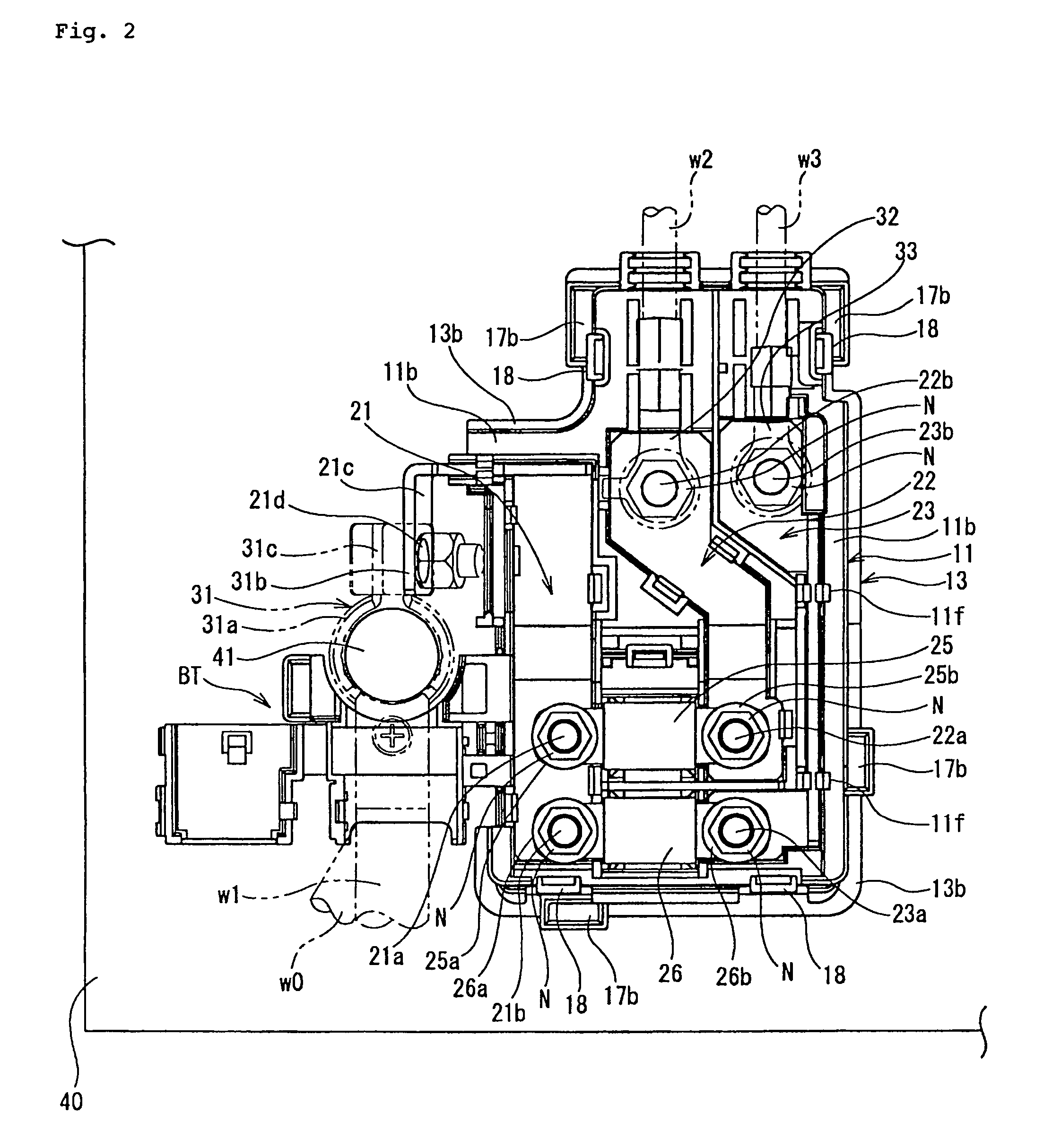
[0023]FIGS. 1 through 5 show a fuse box 10 of the present invention. The fuse box 10 has a case body 11; a plurality of bus bars 21, 22, and 23 provided on the case body 11; fusible links 25, 26 connected with the bus bars 21, 22, and 23; and an upper cover 12 and a lower cover 13 mounted on the case body 11 to cover the upper and lower surfaces thereof, with the case body 11, the upper cover 12, and the lower cover 13 connected with one another. The fuse box 10 is mounted on a battery box 40.

[0024]More specifically, as shown in FIG. 2, one input-side bus bar 21 and two output-side bus bars 22, 23 are disposed on an upper surface of the case body 11. An input terminal 25a of the fusible link 25 and an input terminal 26a of the fusible Ink 26 are fitted on bolts 21a, 21b respectively projected from one side of the input-side bus bar 21 and fastened to the bolts 21a, 21b with nuts N respectively. An output terminal 25b of the fusible link 25 is fitted on a bolt 22a disposed at one sid...

second embodiment

[0041]In the second embodiment, the pressure-reducing gap S and the first watertight portion A and the second watertight portion B sandwiching the pressure-reducing gap S therebetween are disposed at positions on the periphery of the portion where the fusible links 25, 26 requiring a high degree of waterproofness are disposed. Therefore it is possible to constantly secure the waterproofness necessary for the fuse box 10. By not providing other peripheral portions with the waterproof mechanism, it is possible to improve the layout of the fuse box 10 and make it compact.

[0042]FIG. 8 shows the third embodiment of the present invention. The third embodiment is different from the first and second embodiments in that the fuse box of the third embodiment does not have the loner cover and that the waterproof mechanism is constructed of the upper cover 12 and the case body 11.

[0043]More specifically, the lower end surface 12b of the peripheral wall 12a of the upper cover 12 contacts the uppe...

third embodiment

[0044]In the third embodiment, although the lower cover is not provided, the pressure-reducing gap S sandwiched between the first watertight portion A and the second watertight portion B is formed between the peripheral wall 12a of the upper cover 12 and the peripheral wall 11a of tie case body 11. Therefore, the pressure-reducing gap S disperses water which has penetrated into the fuse box at a high pressure from the first watertight portion A and reduces the pressure, thus preventing the water from penetrating into the case body 11 from the second watertight portion B.


PUM


Abstract

In a fuse box mounted on a battery box, a lower end surface of a peripheral wall of an upper cover contacts a bottom wall of a lower cover that is locked to a case body of the fuse box or contacts a bottom wall of the case body to form a first watertight portion. A peripheral wall erect on the bottom wall of the case body is formed by spacing the peripheral wall at a pressure-reducing gap from an inner surface of the upper cover. A rib formed by outwardly bending an upper end of the peripheral wall of the case body is projected toward an inner surface of the peripheral wall of the upper cover to form a second watertight portion. The pressure-reducing gap is interposed between the first watertight portion and the second watertight portion.

Description

FIELD OF THE INVENTION[0001]The present invention relates to a fuse box. More particularly the fuse box is mounted on a battery box. The fuse box accommodates bus bars connected with a battery terminal and fuses connected with the bus bars and has a high waterproof function.DESCRIPTION OF THE RELATED ART[0002]As the conventional watertight construction of the fuse box mounted on vehicles and the like, the construction, shown in FIG. 9, which is disclosed in Japanese Patent Application Laid-Open No. 9-308053 (patent document 1) is known.[0003]As shown in FIG. 9, the electric junction box 1 includes a case body 2 in which the bus bar 6 and the fuse 7 are mounted, the upper cover 3 mounted on the upper surface of the case body 2 to cover the upper surface thereof, and a lower cover 4 mounted on the lower surface of the case body 2 to cover the lower surface thereof. The case body 2 and the upper cover 3 are locked to each other with a locking portion 5a. The case body 2 and the lower c...

Claims


Application Information

Patent Timeline
Patent Type & Authority Patents(United States)
IPC IPC(8): H02G3/08
CPCH01R13/5202H01H85/0026H01H2085/208H01R2201/26Y10S439/949
Inventor KANAZAWA, MASASHI
Owner SUMITOMO WIRING SYST LTD
Why Eureka
Try Eureka