
Headset communication unit

a communication unit and headset technology, applied in the direction of transmission, supra/circum aural earpieces, mouthpiece/microphone attachments, etc., to achieve the effect of simple manner

Inactive Publication Date: 2006-10-31
GN NETCOM
View PDF23 Cites 15 Cited by
  • Summary
  • Abstract
  • Description
  • Claims
  • Application Information

AI Technical Summary

Benefits of technology

[0010]It is thus an object of the invention to provide a communication unit which, when it is not in use, only occupies very little space, which is easy to use, also for a user who is not familiar with the communication unit, and which is of a robust and operationally reliable construction.
[0012]It is hereby achieved that in the first position, the microphone arm will not project outside the extent of the housing, but will lie up against and coincide with this, so that in its unused state the communication unit will not occupy a particularly great deal of space and, furthermore, it can easily be kept for example in a drawer, in a bag, in a pocket or other similar places. Moreover, with the disclosed configuration a relatively simple and robust hinging of the microphone arm to the housing is achieved, since what is involved is merely a single hinge link, so that the microphone arm can be folded out to the position of use in a simple manner.
[0014]As disclosed, it can be expedient for a switch arrangement to be associated with the movement of the microphone arm, which can be used, for example, for coupling the communication unit electrically when the microphone arm is folded out, and conversely for switching off the communication unit when the microphone arm is folded in against the housing. This will be an advantage especially when the communication unit functions in a wireless manner, in that here it is especially necessary to prevent unnecessary current consumption, which can be achieved precisely with the disclosed configuration, where the current consumption will be cut off when the microphone arm is folded in, e.g. when it is taken off the user's head. It will thus not be necessary for the user to have to remember to switch off the communication unit by operating a separate switch button.
[0015]With a particularly expedient embodiment, such as disclosed, a lock- or safety arrangement can be associated with the microphone arm. It can hereby be ensured that the microphone arm will not unintentionally be moved away from the folded-together state, e.g. while it is being kept in a pocket, a bag, the glove compartment of a car or similar places of storage, which could otherwise have the effect that it will consume current, which as mentioned is a disadvantage, especially in connection with wireless configurations. The release arrangement can consist of a purely mechanical device which secures the microphone arm, and which when activated results in the fact that the microphone arm can be folded out. At the same time herewith, the microphone arm can thus activate a switch arrangement as mentioned above. However, the release arrangement can also consist of a mechanical device, which at the same time is coupled to a changeover switch or contact, so that an activation of the release arrangement not only releases the microphone arm but also couples the electrical circuits. Finally, the lock- or safety arrangement can consist of a bi-stable construction of the microphone arm and its suspension, so that the microphone arm, e.g. against a spring pressure, must be forced or moved away from the two stable positions, for example the fully folded-in and the fully folded-out position. It is not until the passage of an unstable point that the movement of the microphone arm becomes easier or possibly completely influenced, e.g. by a spring force, towards the second of the two stable positions. In this way it is similarly ensured that the microphone arm is not unintentionally moved away from the in-active state.
[0017]Furthermore, the communication unit can expediently be configured as disclosed, whereby in connection with a wireless embodiment an antenna is established in association with the housing or in association with the microphone arm, so that it is avoided that a fixed antenna will project outside the extent of the housing when the communication unit is not in use. As disclosed, the antenna can expediently consist of a coating on a surface in or on the housing or the microphone arm, for example on a side of the microphone arm, whereby a suitable antenna can be established in a relatively simple manner.
[0020]Finally, the communication unit can be configured as disclosed, so that there is free choice whether the communication unit is to be worn on the right or on the left ear, in that the user can carry out a changeover to the position in which the communication unit is desired to be worn in a relatively simple manner.

Problems solved by technology

What this known microphone arm thus involves is that it consists of a relatively complicated and herewith also a vulnerable mechanism, which comprises two hinge links and a linear guiding movement and herewith subsequent risk of damage during use.
Moreover, the users of this known earset must make themselves familiar with a relatively complex procedure for taking the earset into use and its adjustment, in that the microphone arm must first be slid out of the guideway groove, after which the two link stays must be folded out, and finally after which a suitable position of use must be set by adjustment of the two hinges, i.e. partly the hinge between the two link stays and partly the hinge between the second link stay and the housing.

Method used


Image

  • Headset communication unit
  • Headset communication unit
  • Headset communication unit

Examples


Embodiment Construction

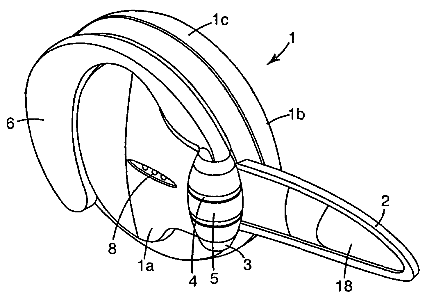
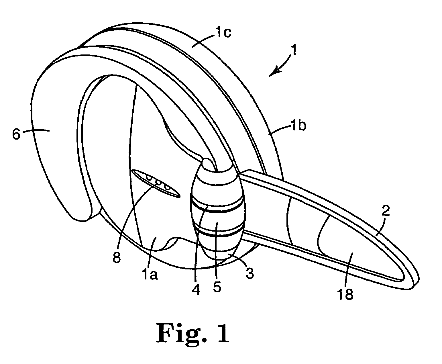
[0049]An embodiment of a communication unit according to the invention is shown in perspective and in its state of use in FIG. 1, and as will be seen the unit consists of a housing, which is indicated in general by the reference FIG. 1. This housing is configured as a flat capsule with slightly convex side surfaces, i.e. an inner side surface 1a and an outer side surface 1b, and with an annular edge surface 1c, which is similarly slightly convex. The extent of the side surfaces of the housing is of the same order as or less than an ear, so that the housing can easily be worn by a user without any inconvenience.

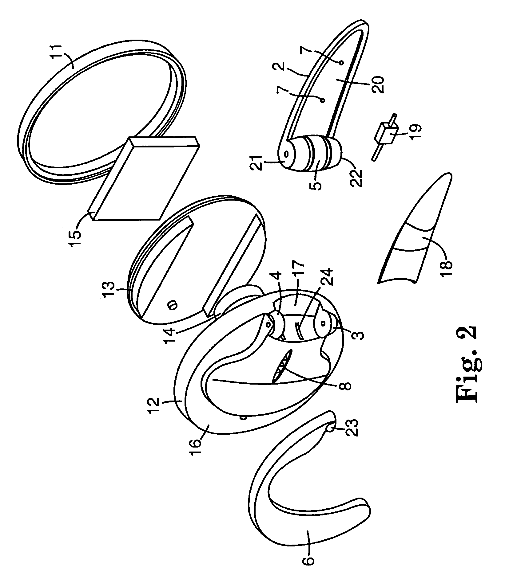
[0050]A microphone tongue or microphone arm 2, as it is also called in the following, is extending out from the housing, and this microphone arm is secured to the housing by means of two hinge pins 3 and 4 which are integrated parts of the housing 1, and which extend from the side surface 1a in the vicinity of the edge surface 1c or in the interface area between these two surf...


PUM


Abstract

Communication unit comprising a housing in which at least one transducer is placed, and on which a microphone arm is suspended. The housing also has means, such as an ear hook, for fastening the communication unit to the head of a user. The microphone arm is pivotally connected to the housing by a hinge link, and at an outer area of the housing, so that the microphone arm can be moved between a first position in which it lies up against the housing, and a second position in which it extends away from the housing. The microphone arm has a length, which in the main is less than or of the same order as the greatest extent of the housing, so that in the folded-in state the microphone arm does not project out over the circumference of the housing. The communication unit can be used on both the right and the left side of the head, in that the ear hook (6) can be suspended in two different positions, corresponding to the communication unit being worn on the right or the left ear, respectively.

Description

[0001]This application is a divisional of application Ser. No. 09 / 813,103, filed Mar. 19, 2001. This application is incorporated herein by reference.TECHNICAL FIELD[0002]1. Field of the Invention[0003]The invention concerns a headset communication unit which comprises a housing in which at least one transducer is placed, and on which a microphone arm is suspended, said housing also having means for securing the communication unit to the head of a user. In the preferred construction, the headset is intended to be in wireless connection with some kind of other base unit, such as a cell phone, and communications would preferably follow the “Bluetooth” protocol. Of course, a person skilled in the art could modify the structure shown to make a wire connection with a base unit.[0004]Such a communication unit is most often used in connection with telephony, where a telephone user who talks over the telephone often and / or engages in long telephone conversations, can use such a unit in the f...

Claims


Application Information

Patent Timeline
Patent Type & Authority Patents(United States)
IPC IPC(8): H04M1/00H04B1/38H04M9/00H04M1/05H04R1/08H04R1/10
CPCH04M1/05H04R1/083H04R1/1066H04M2250/02H04R1/1008H04R1/1041H04R1/105H04R1/1058H04R2201/107H04R2201/109H04R2420/07H04R1/10
Inventor BODLEY, MARTIN REEDSMITH, IAN PAULLYMAN, STEPHEN R.BJERRUM-NIESE, CHRISTIANWOJCIAK, PAULPEDERSON, CHARLES L.
Owner GN NETCOM
Learn More