Optical repeating system and optical amplifying repeater control method

Active Publication Date: 2006-10-31
MITSUBISHI ELECTRIC CORP +2
View PDF8 Cites 5 Cited by
  • Summary
  • Abstract
  • Description
  • Claims
  • Application Information

AI Technical Summary

Benefits of technology

[0015]The present invention is implemented to solve the foregoing problem. It is therefore an object of the present invention to provide an optical repeating s

Problems solved by technology

With the foregoing configuration, the conventional optical repeating system has a problem in that it difficult for the control program that controls the optical amplifying repeaters 3 to restart its normal operation once it has fallen into a trouble where it can hardly continue its normal processing becau

Method used


Image

  • Optical repeating system and optical amplifying repeater control method
  • Optical repeating system and optical amplifying repeater control method
  • Optical repeating system and optical amplifying repeater control method

Examples


embodiment 2

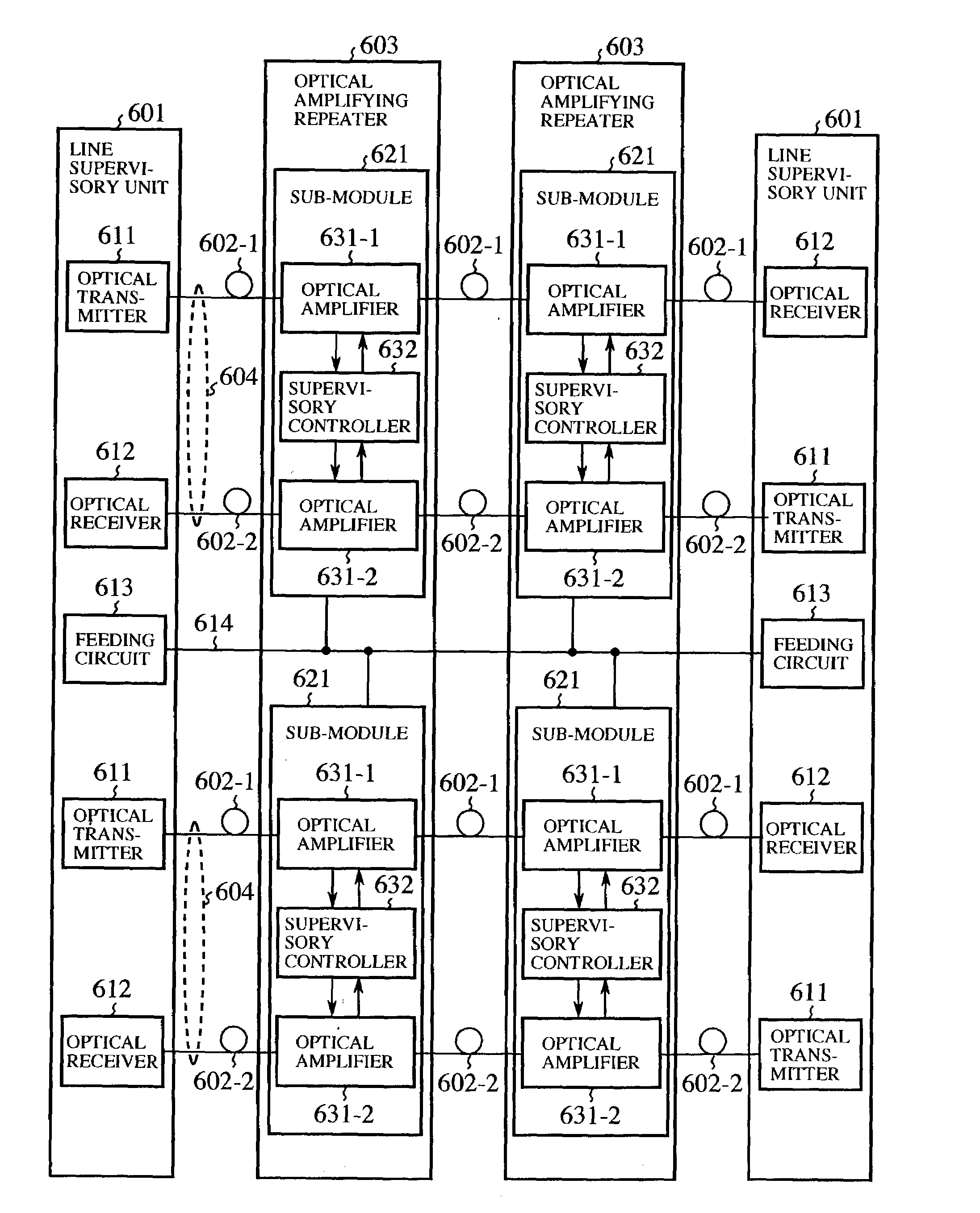
[0061]The present embodiment 2 of the optical repeating system in accordance with the present invention is configured such that each sub-module 621 switches when necessary the optical transmission line for transmitting the second sub-signal to the alternative optical transmission line in response to the control command via the alternative sub-module 621.

[0062]Specifically, when there are two pairs of the uplink and downlink optical transmission lines as shown in FIG. 1, and if one pair of the optical transmission lines has a failure, the controller 652 of the supervisory controller 632 in the sub-module 621 of the faulty system controls the modem unit 651 of the supervisory controller 632 in the sub-module 621 of the faultless system, so that the second sub-signal is transmitted to the optical receivers 612 to which the second sub-signal cannot be transmitted via the faulty system.

[0063]Since the remaining configuration and the operation of the embodiment 2 of the optical repeating ...


PUM


Abstract

An optical repeating system includes an optical transmitter and an optical amplifying repeater. The optical transmitter transmits a supervisory command and a control command to the optical amplifying repeater as a first sub-signal. The supervisory command is a command to supervise internal circuits of the optical amplifying repeater, and the control command is a command to control the optical amplifying repeater. The optical amplifying repeater includes multiple sub-modules each for amplifying and repeating main signals on multiple sets of optical transmission lines. When receiving the supervisory command via the optical transmission line, each sub-module transmits a supervisory signal indicating the supervisory result associated with the supervisory command to an optical receiver as a second sub-signal. In addition, when receiving a predetermined control command via the optical transmission line, each sub-module initializes another sub-module of the multiple sub-modules in response to the predetermined control command. The optical amplifying repeater can restart its control program even when it has fallen into a state where it is difficult to continue to execute the normal operation in accordance with the control program because of some exception or the like.

Description

BACKGROUND OF THE INVENTION[0001]1. Field of the Invention[0002]The present invention relates to an optical repeating system that comprises multiple sets of optical transmission lines, optical transmitters and optical receivers for transferring main signals through each set of optical transmission lines, and optical amplifying repeaters for amplifying and repeating the main signal with optical amplifiers at intermediate positions on the multiple sets of optical transmission lines, and to an optical amplifying repeater control method for controlling the optical amplifying repeaters.[0003]2. Description of Related Art[0004]FIG. 4 is a block diagram showing a configuration of a conventional optical repeating system disclosed in Japanese patent No. 2,716,882. In FIG. 4, the reference numeral 1 designates an optical transmitter for transmitting a main signal conveying information and a first sub-signal bearing a command for an optical amplifying repeater 3; 2 designates an optical fiber ...

Claims


Application Information

Patent Timeline
IPC IPC(8): H04B10/02H04B10/07H04B10/032H04B10/077H04B10/29H04B10/297H04B17/40
CPCH04B10/0777H04B10/2918H04B2210/074H04B10/298
Inventor KASAHARA, YASUNORIGOTO, HIDEKIMIZUOCHI, TAKASHISHIMOMURA, KENKICHISUZUKI, MASATOSHIHORIUCHI, YUKIOISHII, DAISHIKAWAZAWA, TOSHIO
Owner MITSUBISHI ELECTRIC CORP
Why Eureka
Try Eureka