Near-field scanning microwave microscope using dielectric resonator

a microwave microscope and dielectric resonator technology, applied in the field of near-field scanning microwave microscopes, can solve the problems of limited resolution of optical microscopes for measuring the shape of nano-sized samples, limit in obtaining maximum sensitivity, etc., to enhance sensitivity, resolution and function, and minimize the bad influences of external environments

Active Publication Date: 2006-10-31
IND UNIV COOP FOUND SOGANG UNIV
View PDF2 Cites 18 Cited by
  • Summary
  • Abstract
  • Description
  • Claims
  • Application Information

AI Technical Summary

Benefits of technology

[0017]The present invention provides a near-field microscope using a dielectric resonator, which makes it possible to minimize the bad influences of external environments, and to enhance its sensitivity, resolution and function by adjusting the distance between a sample and an apex of a probe.
[0018]The present invention also provides a near-field microscope using a dielectric resonator, which makes it possible to extend the range of searchable samples by optimally designing the shape of the tip in a dielectric resonator, and to adjust a frequency by installing a tuning screw on the resonator.
[0019]The present invention also provides a near-field microscope using a dielectric resonator, which makes it possible to minimize its volume, to easily adjust the distance between a probe and a sample by using the probe and a tuning fork, and to observe the sample in various directions.

Problems solved by technology

An optical microscope for measuring the shape of a nanosize sample has a limited resolution due to a diffraction limit because it observes the shape of an object using light.
That is, an object having a size smaller than the half of a light wavelength cannot be optically measured due to the diffraction limit.
Accordingly, a resonance frequency of the near-field microscope must be limited to a specific frequency of the microwave band, whereby a limit exists in obtaining the maximum sensitivity.
Accordingly, various wave modes for measuring various optical characteristics of the sample cannot be used in the above microscope.
That is, the coaxial cable resonator 13 inevitably has a length of about 2 m. Accordingly, a near-field optical microscope using a coaxial cable resonator is very large in volume, and is thus unsuitable for commercialization.
However, the conventional near-field microscope using a waveguide slit has drawbacks in that a light loss is increased and its resolution is degraded because light having passed through the slit 115 spreads.
Even a conventional near-field microscope using a improved waveguide structure is susceptible to external environments, is large in volume, cannot be easily assembled, and cannot measure various wave modes and various samples because a device for adjusting a distance between a sample and an end of a probe is not easily installed.

Method used


Image

  • Near-field scanning microwave microscope using dielectric resonator
  • Near-field scanning microwave microscope using dielectric resonator
  • Near-field scanning microwave microscope using dielectric resonator

Examples


Embodiment Construction

[0053]The present invention will now be described more fully with reference to the accompanying drawings, in which exemplary embodiments of the invention are shown.

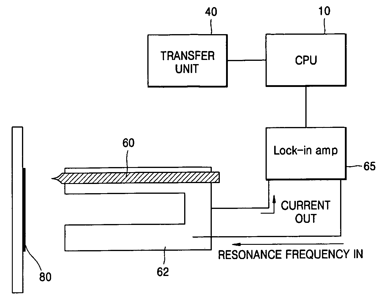
[0054]FIG. 3 is a schematic block diagram of a near-field microscope using a dielectric resonator according to an embodiment of the present invention.

[0055]Referring to FIG. 3, the inventive near-field microscope includes a central processing unit 10, a wave source 20, a detector 30, a dielectric resonator moving unit 40, a dielectric resonator 50, a probe 60, and an image processing unit 70.

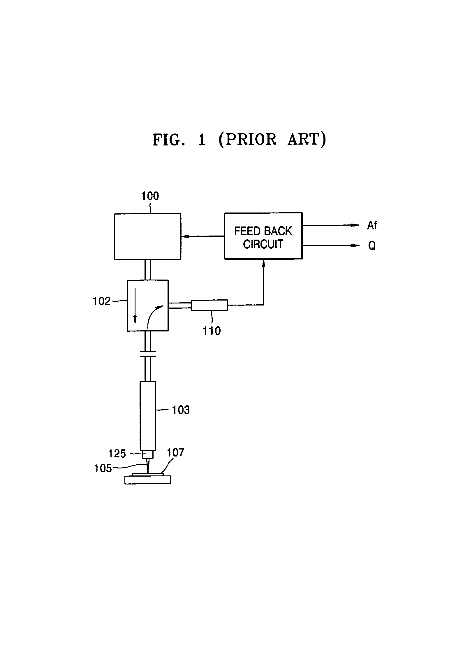
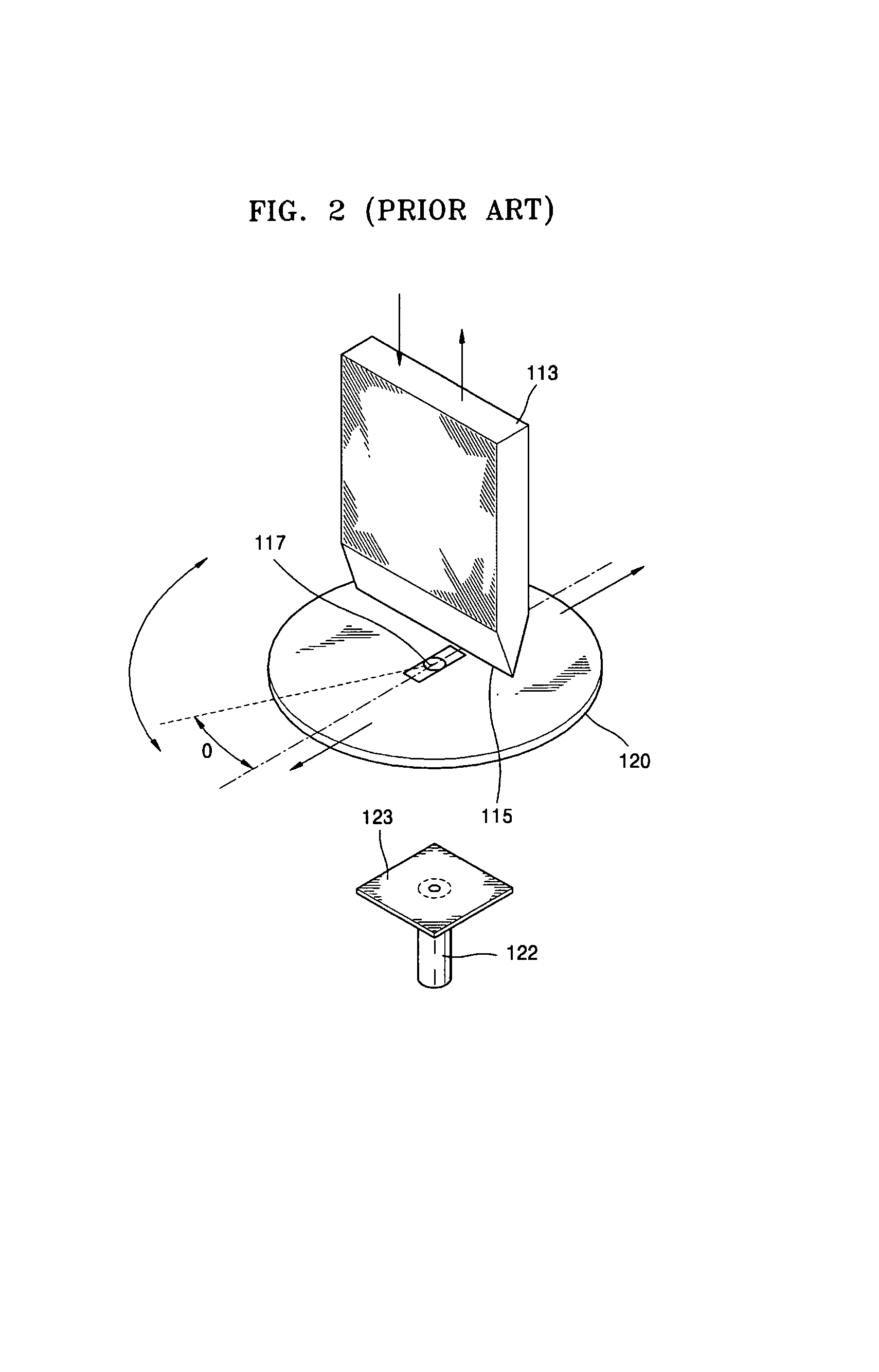
[0056]As aforementioned, the conventional near-field microscope using a coaxial cable resonator has a problem in that searchable samples are limited in type or scope, because it can use only a TEM mode. Also, the conventional near-field microscope using a waveguide slit has a problem in that its resolution is degraded. Accordingly, the inventive near-field microscope uses a dielectric resonator to solve the above problems of the conve...


PUM


Abstract

Provided is a near-field microscope using a dielectric resonator, which makes it possible to minimize influences by external environments, and to enhance its sensitivity, resolution and function by adjusting the distance between a sample and an apex of a probe. The near-field microscope includes a wave source, a dielectric resonator, a probe, a distance adjusting unit, and a detector. The wave source generates a wave, and a frequency of the wave is adjustable by the wave source. The dielectric resonator propagates the wave from the wave source, and a resonance frequency, impedance, a Q factor and an electromagnetic wave mode of the wave is freely adjustable. The probe scans the wave output from the dielectric resonator on a sample. The distance adjusting unit measures a distance between the probe and the sample and maintains the distance to a predetermined value. The detector detects a wave that propagates through the probe, interacts with the sample and then propagates through the probe and the dielectric resonator.

Description

CROSS-REFERENCE TO RELATED PATENT APPLICATION[0001]This application claims the benefit of Korean Patent Application No. 10-2004-0030469, filed on Apr. 30, 2004, in the Korean Intellectual Property Office, the disclosure of which is incorporated herein in its entirety by reference.BACKGROUND OF THE INVENTION[0002]1. Field of the Invention[0003]The present invention relates to a near-field scanning microwave microscope, and more particularly, to a near-field scanning microwave microscope, which can minimize the bad influence of temperature or external environments thereon and enhance its sensitivity and resolution by connecting a probe to a dielectric resonator.[0004]2. Description of the Related Art[0005]An optical microscope for measuring the shape of a nanosize sample has a limited resolution due to a diffraction limit because it observes the shape of an object using light. That is, an object having a size smaller than the half of a light wavelength cannot be optically measured due...

Claims


Application Information

Patent Timeline
Patent Type & Authority Patents(United States)
IPC IPC(8): G01C25/00G06F19/00G01B5/28G01Q10/00G01Q30/04G01Q30/18G01Q60/18G01Q60/22G02B21/00H01P7/10
CPCB82Y20/00B82Y35/00G01Q60/22A47L15/0063A47L15/4293A47L2501/26
Inventor LEE, KIE JINKIM, JOO YOUNGYOO, HYUN JUNYANG, JONG ILKIM, SONG HUI
Owner IND UNIV COOP FOUND SOGANG UNIV
Why Eureka
Try Eureka