Anti-entrapment systems for preventing objects from being entrapped by translating devices

a technology of anti-entrapment and translating device, which is applied in the direction of counting objects on conveyors, pulse techniques, instruments, etc., can solve the problems of requiring a relatively large amount of object pinching, and achieve the effect of preventing any object pinching

Inactive Publication Date: 2006-11-07
UUSI
View PDF87 Cites 99 Cited by
  • Summary
  • Abstract
  • Description
  • Claims
  • Application Information

AI Technical Summary

Benefits of technology

[0008]Accordingly, it is an object of the present invention to provide an anti-entrapment system having a sensor that detects a translating device pinching an object as soon as the translating device has applied a relatively small amount of pinching to the object and / or detects the presence of the object within an opening which may be closed by the translating device in order to prevent any pinching of the object by the translating device.
[0012]Also, in carrying out the above object and other objects, the present invention provides a third anti-entrapment system. The third system includes a sensor positioned adjacent to a translating device. The sensor has an electrically non-conductive elastomer outer jacket having an interior filled with air, first and second electrically conductive elastomer carriers connected to opposite sides of the outer jacket and positioned within the air interior of the outer jacket, and first and second electrically conductive wires respectively sheathed in the first and second carriers. The carriers contact one another upon a compression force being applied to the outer jacket such that the configuration of the air interior changes and the carriers move towards and contact one another. A controller is connected to the wires for monitoring contact between the carriers. Upon such contact of the carriers the controller prevents the translating device from moving in a selected direction in order to prevent the translating device from entrapping an object. The third system further includes an elastomer base which a portion of the outer jacket rests against. The elastomer base has a higher compression force compared to the compression force of the outer jacket required for changing the configuration of the air interior thereby providing an over-travel feature to prevent inertia from the translating device from causing high forces against an entrapped object.
[0013]Further, in carrying out the above object and other objects, the present invention provides a fourth anti-entrapment system. The fourth system includes a sensor positioned adjacent to a translating device. The sensor has an electrically non-conductive elastomer outer jacket having an interior filled with an electrically conductive elastomer material, first and second electrically conductive elastomer carriers connected to opposite sides of the outer jacket and positioned within the interior of the outer jacket such that the carriers are separated from the elastomer material by respective air spaces, and first and second electrically conductive wires respectively sheathed in the first and second carriers. The carriers electrically contact one another via the elastomer material upon a compression force being applied to the outer jacket such that the configuration of the air spaces change and the carriers move towards and contact the elastomer material. A controller is connected to the wires for monitoring contact between the carriers and the elastomer material, wherein upon such contact the controller prevents the translating device from moving in a selected direction in order to prevent the translating device from entrapping an object. The elastomer material continues to compress after the carriers have contacted the elastomer material thereby providing an over-travel feature to prevent inertia from the translating device from causing high forces against an entrapped object.

Problems solved by technology

A problem with these types of pinch sensors is that they require a relatively large amount of pinching of the object to take place before they detect pinching of the object.

Method used


Image

  • Anti-entrapment systems for preventing objects from being entrapped by translating devices
  • Anti-entrapment systems for preventing objects from being entrapped by translating devices
  • Anti-entrapment systems for preventing objects from being entrapped by translating devices

Examples


Embodiment Construction

)

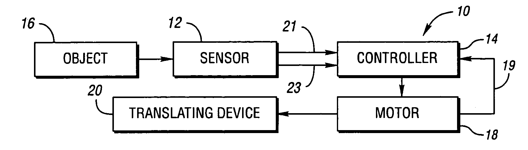
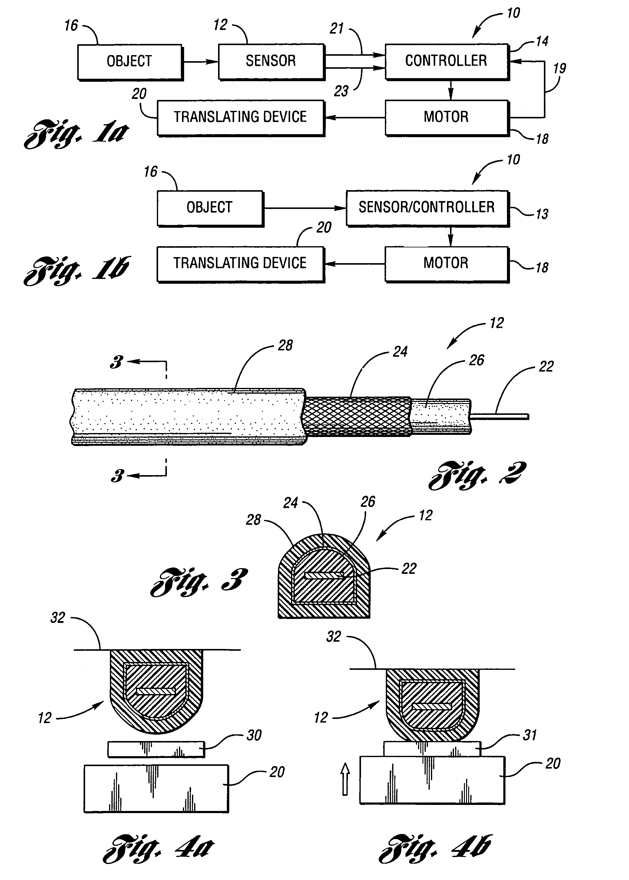
[0083]Referring now to FIG. 1A, an anti-entrapment system 10 in accordance with the present invention is shown. Anti-entrapment system 10 includes a sensor 12 and a controller 14. Sensor 12 is a capacitance sensor that is operable to detect touching by an object 16 to the sensor and / or the presence of the object near the sensor. In response to an object 16 touching sensor 12, the capacitance of the sensor changes. Likewise, in response to an object 16 that is electrically conductive, including the human body, coming within the proximity of sensor 12, the capacitance of the sensor changes even without the object actually touching, or applying any force, to the sensor. This provides for zero force detection of a human body part before contact is made to the body part. As such, sensor 12 is a contact and a non-contact sensor.

[0084]Controller 14 controls a motor 18 associated with a translating device 20 such as a window, sliding door, sunroof, etc. in order to move the translating dev...


PUM


Abstract

An anti-entrapment system for preventing an object from being entrapped by a translating device includes a capacitance sensor positioned adjacent to the translating device. The sensor has first and second conductors separated by a separation distance, a compressible dielectric element interposed between the conductors, and a non-conductive elastomer outer jacket encasing the conductors and the dielectric element. The sensor having a capacitance dependent upon the separation distance between the conductors. The capacitance changes in response to the separation distance changing as a result of the dielectric element compressing in response to a first object touching the outer jacket, and in response to a second conductive object coming into proximity with at least one of the conductors. A controller controls the translating device as a function of the capacitance in order to prevent the translating device from entrapping either object.

Description

CROSS-REFERENCE TO RELATED APPLICATIONS[0001]This application is a continuation-in-part of U.S. application Ser. No. 10 / 262,446, filed Sep. 30, 2002, now U.S. Pat. No. 6,782,759, which is a continuation-in-part of U.S. application Ser. No. 09 / 901,883, filed on Jul. 9, 2001, now U.S. Pat. No. 6,499,359.BACKGROUND OF THE INVENTION[0002]1. Field of the Invention[0003]The present invention relates to an anti-entrapment system provided with a capacitance sensor for preventing entrapment of an object.[0004]2. Background Art[0005]Anti-entrapment systems use various types of sensors to detect pinching of an object such as a human body part. For example, in automobiles, sensors are used for pinch sensing at electrically operated doors, windows, hatches, decks, hoods, lids, and the like.[0006]A pinch sensor detects pinching an object by a translating device such as a window, door, sunroof, etc. In operation, the pinch sensor generates a pinch sensor signal in response to the object such as a ...

Claims


Application Information

Patent Timeline
Patent Type & Authority Patents(United States)
IPC IPC(8): H01J40/14B60N2/00B60R21/01B60R21/015E05F15/00G01D5/241H03K17/96
CPCB60N2/002G01D5/2417H03K17/955H03K17/962E05F15/46B60R21/01532B60R21/01516B60R21/0154H03K17/975E05Y2400/66E05Y2900/548H03K2017/9602H03K2217/96078
Inventor SHANK, DAVID W.PERRIN, RANDALL L.WASHELESKI, JOHN M.
Owner UUSI
Why Eureka
Try Eureka