Valve for a Subsea Pressure Canister

Inactive Publication Date: 2015-09-10
SIEMENS AS
View PDF5 Cites 3 Cited by
  • Summary
  • Abstract
  • Description
  • Claims
  • Application Information

AI Technical Summary

Benefits of technology

[0014]For opening the valve, the plug is to be removed and, instead, an adapter coupling the valve to a fluid conduit may be inserted into the cylindrical sealing hole at the second end of the stem. Further, the stem is to be moved into the open position. Thus, a fluid communication between the first port of the valve body and the fluid conduit is achieved for filling for example SF6 gas into the subsea pressure canister or for evacuating the subsea pressure canister. The adapter is fluid tight coupled to the sealing hole by the further seal. The seal arranged between the outer circumferential surface of the stem and the sealing section of the passage provides a sealing between the stem and the valve body and, therefore, a discharge of fluid, especially of SF6 gas, into the environment may be avoided.
[0015]According to another embodiment, and as described above, the seal may be arranged in a circumferential groove at the outer circumferential surface of the stem and the sealing section of the passage may be extending in the longitudinal direction at least from the position at which the seal is arranged in the closed position to at least the position at which the seal is arranged in the open position. In other words, the seal provides a sealing between the stem and the valve body in every position of the stem between the open and clo

Problems solved by technology

A major obstacle in deep water is the extreme high pressure experienced by the equipment at these water depths.
Therefore, the pressure outside the canister may become extremely large, for example as h

Method used


Image

  • Valve for a Subsea Pressure Canister
  • Valve for a Subsea Pressure Canister
  • Valve for a Subsea Pressure Canister

Examples


Embodiment Construction

[0028]In the following, exemplary embodiments will be described in more detail. It is to be understood that the features of the various exemplary embodiments described herein may be combined with each other unless specifically noted otherwise. Same reference signs in the various drawings refer to similar or identical components. For clarity reasons, in some of the drawings, not every component is designated by a corresponding reference sign and these components may be referenced in the following detailed description by corresponding reference signs defined in other drawings.

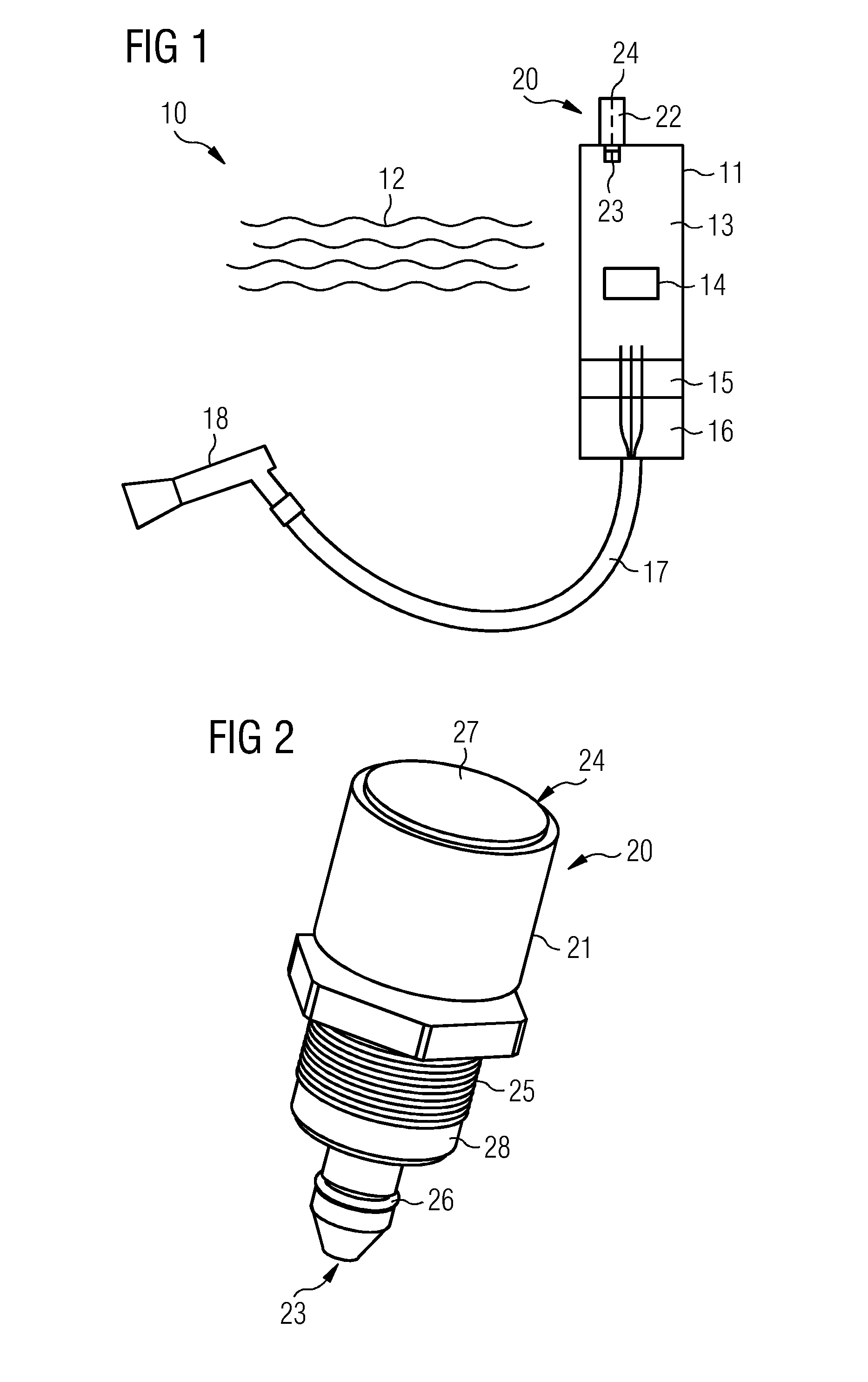
[0029]FIG. 1 schematically depicts a subsea pressure canister 11 in a subsea environment 10. The subsea canister 11 or subsea vessel 11 is used for housing components 14 in an interior 13 for protecting the components 14 from high pressure present in deep sea water 12. For coupling the components 14 with other equipment, the subsea canister 11 may include a port 16, (for example, an oil-filled pressure compensate...


PUM


Abstract

A valve for a subsea pressure canister for controlling a fluid flow includes a valve body having a passage extending in a longitudinal direction. At an inner surface of the passage, a valve seat, a sealing section, and a threaded section are formed. A stem is arranged within the passage and movable in the longitudinal direction between a closed position and an open position. The stem includes a valve member to provide a sealing between the valve seat and the valve member in the closed position. A seal is arranged between an outer circumferential surface of the stem and the sealing section. An actuator device includes a threaded section engaged with the threaded section of the passage. The actuator device includes a coupling element for coupling the actuator device to the stem to urge the stem in the longitudinal direction upon the longitudinal movement of the actuator device.

Description

CROSS-REFERENCE TO RELATED APPLICATIONS[0001]This application claims the benefit of EP 14157554.8, filed on Mar. 4, 2014, which is hereby incorporated by reference in its entirety.TECHNICAL FIELD[0002]The present embodiments relate to a valve for a subsea pressure canister, in particular, to a valve for controlling a fluid flow into the subsea pressure canister or out of the subsea pressure canister, for example, for filling the subsea pressure canister with a gas like SF6 or for removing the gas from the canister. The valve includes a double sealing including at least a metal seal.BACKGROUND[0003]For subsea applications, (e.g., subsea oil production, subsea energy transmission, or subsea telecommunications), equipment to be operated subsea is configured for this harsh environment. A major obstacle in deep water is the extreme high pressure experienced by the equipment at these water depths. Accordingly, pressure-resistant vessels, so-called pressure canisters, may be used to protec...

Claims


Application Information

Patent Timeline
IPC IPC(8): F16K1/30F17C5/06F16K1/42F16K1/02F16K1/38
CPCF16K1/30F16K1/02F17C5/06F16K1/42F16K1/308F16K1/38F16K1/12
Inventor ESPEDALEN, HANS
Owner SIEMENS AS
Why Eureka
Try Eureka