Flame simulating assembly

a technology flame simulating assembly, which is applied in the field of flame simulating assembly, can solve the problems of insufficient thickness of the interior wall of the two conventional back-to-back units, the inability to combine two conventional flame simulating assemblies to form a two-sided flame simulating assembly, and the inability to meet the requirements of the purpos

Inactive Publication Date: 2006-11-14
DIMPLEX NORTH AMERICA
View PDF83 Cites 42 Cited by
  • Summary
  • Abstract
  • Description
  • Claims
  • Application Information

AI Technical Summary

Benefits of technology

[0141]It will be evident to those skilled in the art that the invention can take many forms, and that such forms are within the scope of the invention as claimed. Therefore, the spirit and scope of the appended claims should not be limited to the description of the preferred versions contained herein.

Problems solved by technology

First, combining two conventional flame simulating assemblies to form a two-sided flame simulating assembly is only feasible where the interior wall in which the conventional flame simulating assemblies are to be positioned is sufficiently thick to receive them.
Second, using two conventional flame simulating assemblies back-to-back is relatively expensive, as all of the materials and controls for each of the conventional units are duplicated.
In addition, because two conventional units positioned back-to-back are relatively broad, an interior wall in which the two conventional back-to-back units are received often has barely enough thickness for the purpose.
This is undesirable because, in general, where there is more distance between the observer and the screen, the simulated flames tend to be perceived by the observer as being more realistic.
Achieving any additional or somewhat improved effects is not feasible where two conventional flame simulating assemblies are combined.

Method used


Image

  • Flame simulating assembly
  • Flame simulating assembly
  • Flame simulating assembly

Examples


Embodiment Construction

)

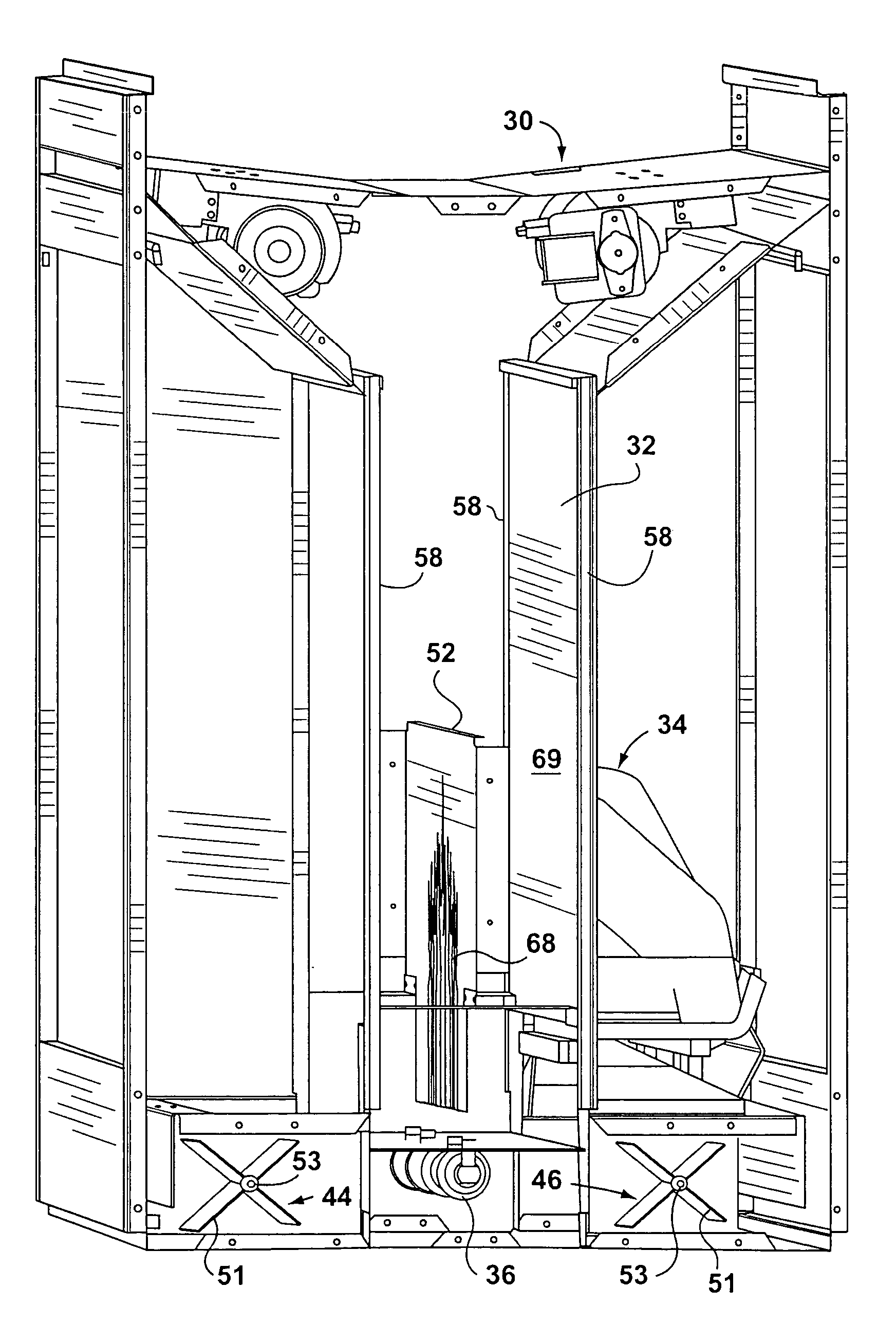
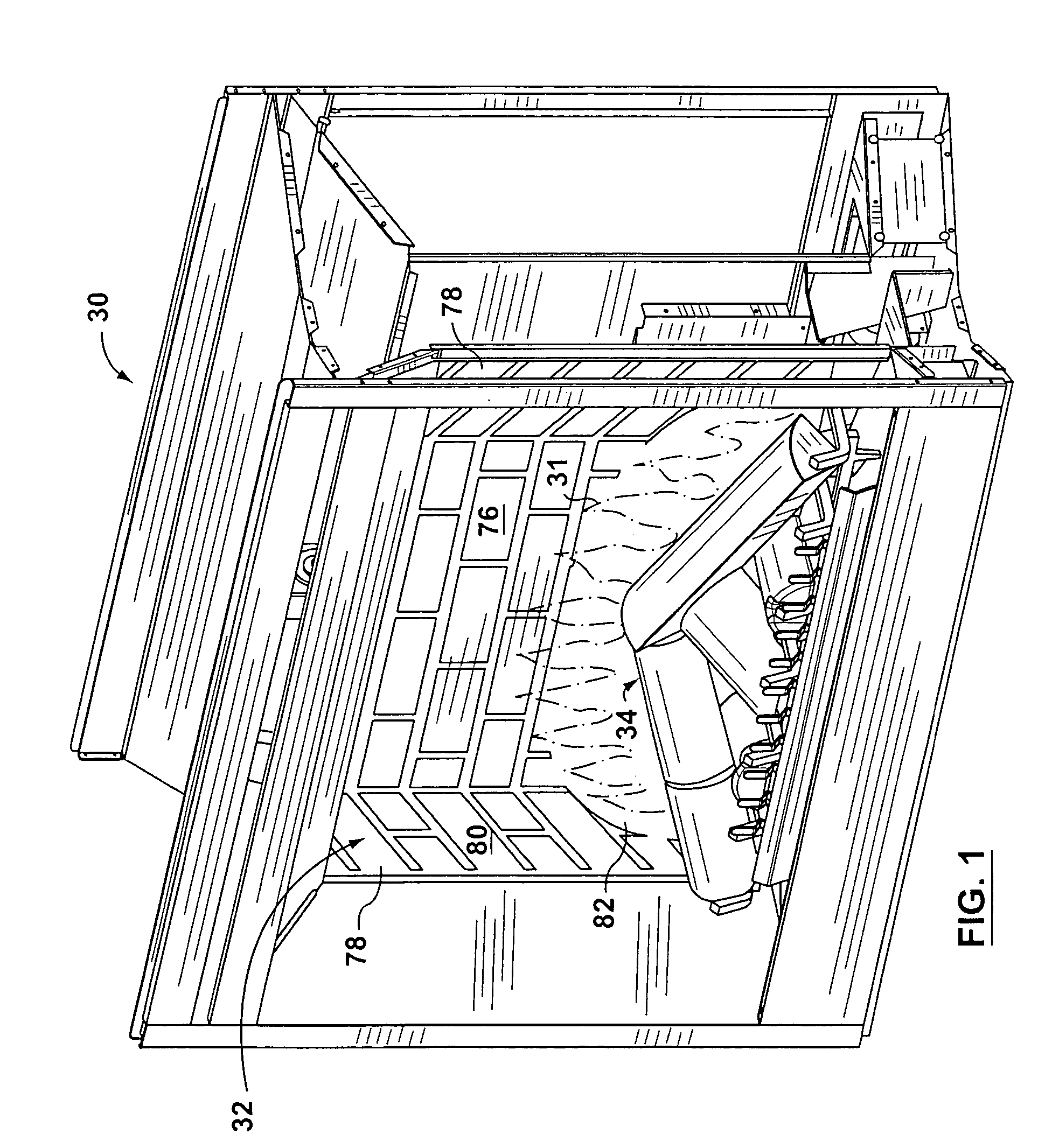
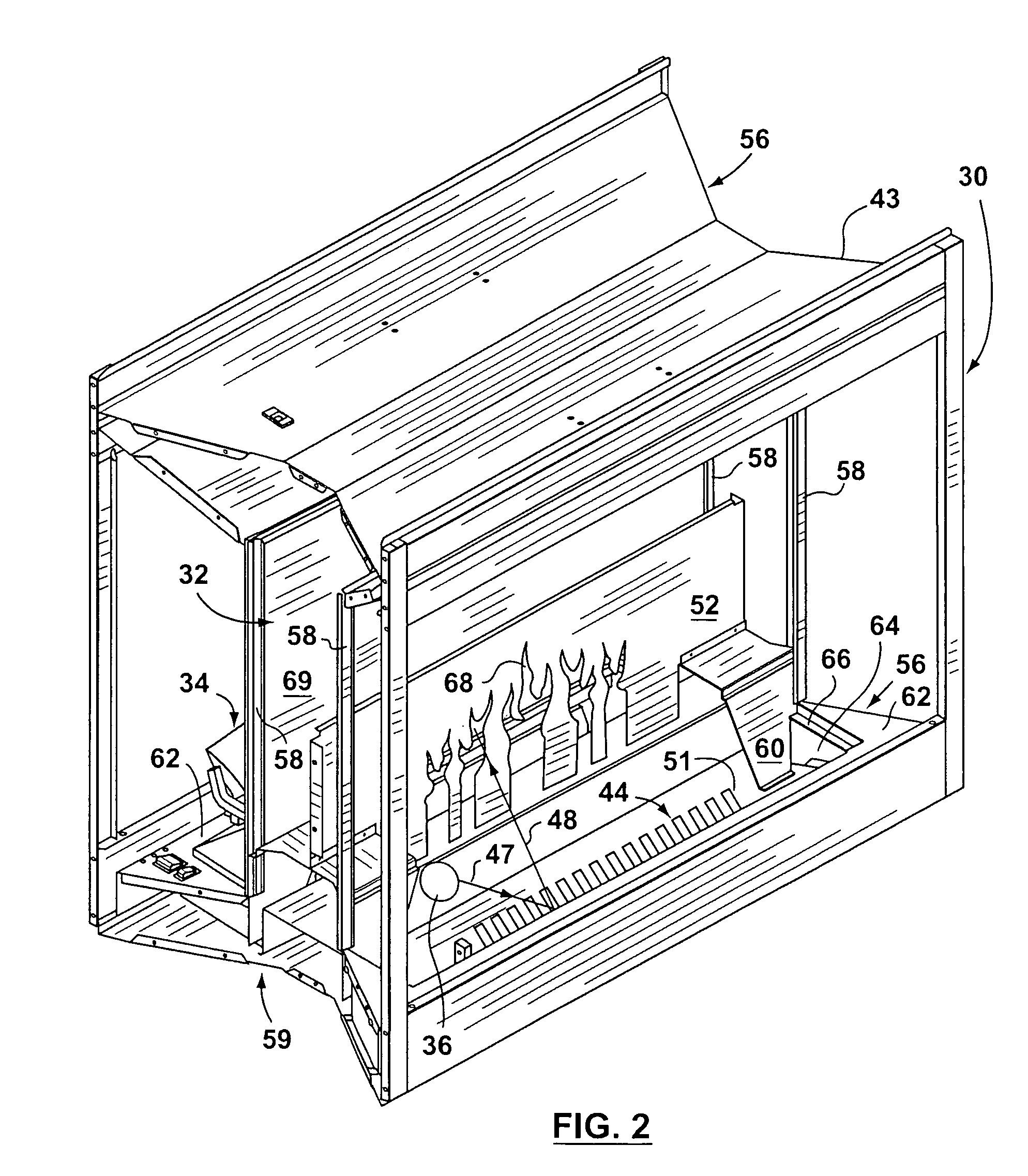
[0055]Reference is first made to FIGS. 1–7 to describe a preferred embodiment of a flame simulating assembly indicated generally by the numeral 30 in accordance with the invention. The flame simulating assembly 30 is for providing one or more images of flames 31 and includes one or more light sources 36, a first screen 32, and a second screen 38 (FIG. 5). In the preferred embodiment, the first screen 32 is positioned in a first path of light 55 (represented by arrows 47, 48, shown in FIG. 5) from the light source 36, and the second screen 38 is positioned in a second path of light 57 (represented by arrows 49, 50, shown in FIG. 5) from the light source 36, as will be described. The first screen 32 is adapted to receive light from the light source 36 to form the image of flames 31, which is transmitted through the first screen 32. In addition, the second screen 38 is adapted to receive light from the light source 36 to form the image of flames 31, which is transmitted through the se...


PUM


Abstract

A flame simulating assembly for providing one or more images of flames. The flame simulating assembly has a light source, a first screen, and a second screen. Each of the first and second screens is positioned in a path of light from the light source. Also, each of the first and second screens is adapted to receive light from the light source to form one or more images of flames transmittable through the screens respectively.

Description

FIELD OF THE INVENTION[0001]The present invention relates to a flame simulating assembly for providing one or more images of flames, and more particularly, a flame simulating assembly for transmitting one or more images of flames through two screens.BACKGROUND OF THE INVENTION[0002]Various types of flame simulating assemblies are known. Often, a flame simulating assembly is designed to be included in an electric fireplace, to simulate a fire in a real fireplace in which wood or coal is burned. For example, U.S. Pat. No. 4,965,707 (Butterfield) discloses a simulated flame system for an electric fireplace in which a light source is combined with billowing ribbons to simulate flames. The effect resulting generally resembles flames from a coal fuel source more than flames from a wood fuel source. The flames for burning wooden logs tend to be more active and extend higher above the fuel source.[0003]On occasion, a two-sided flame simulating assembly is needed. The need typically arises w...

Claims


Application Information

Patent Timeline
Patent Type & Authority Patents(United States)
IPC IPC(8): G09F19/00F24C7/00
CPCF24C7/004
Inventor HESS, KRISTOFFERSTINSON, KELLYADAMCZYK, RICHARD
Owner DIMPLEX NORTH AMERICA
Why Eureka
Try Eureka