
Stand-up display

a stand-up display and display technology, applied in the field of stand-up displays, can solve the problems of increased display cost, unwieldy and expensive transportation, and the need for skilled assemblers, and achieve the effects of improving the effect of display, transporting, and facilitating storag

Active Publication Date: 2006-11-14
INNOMARK COMM
View PDF28 Cites 53 Cited by
  • Summary
  • Abstract
  • Description
  • Claims
  • Application Information

AI Technical Summary

Benefits of technology

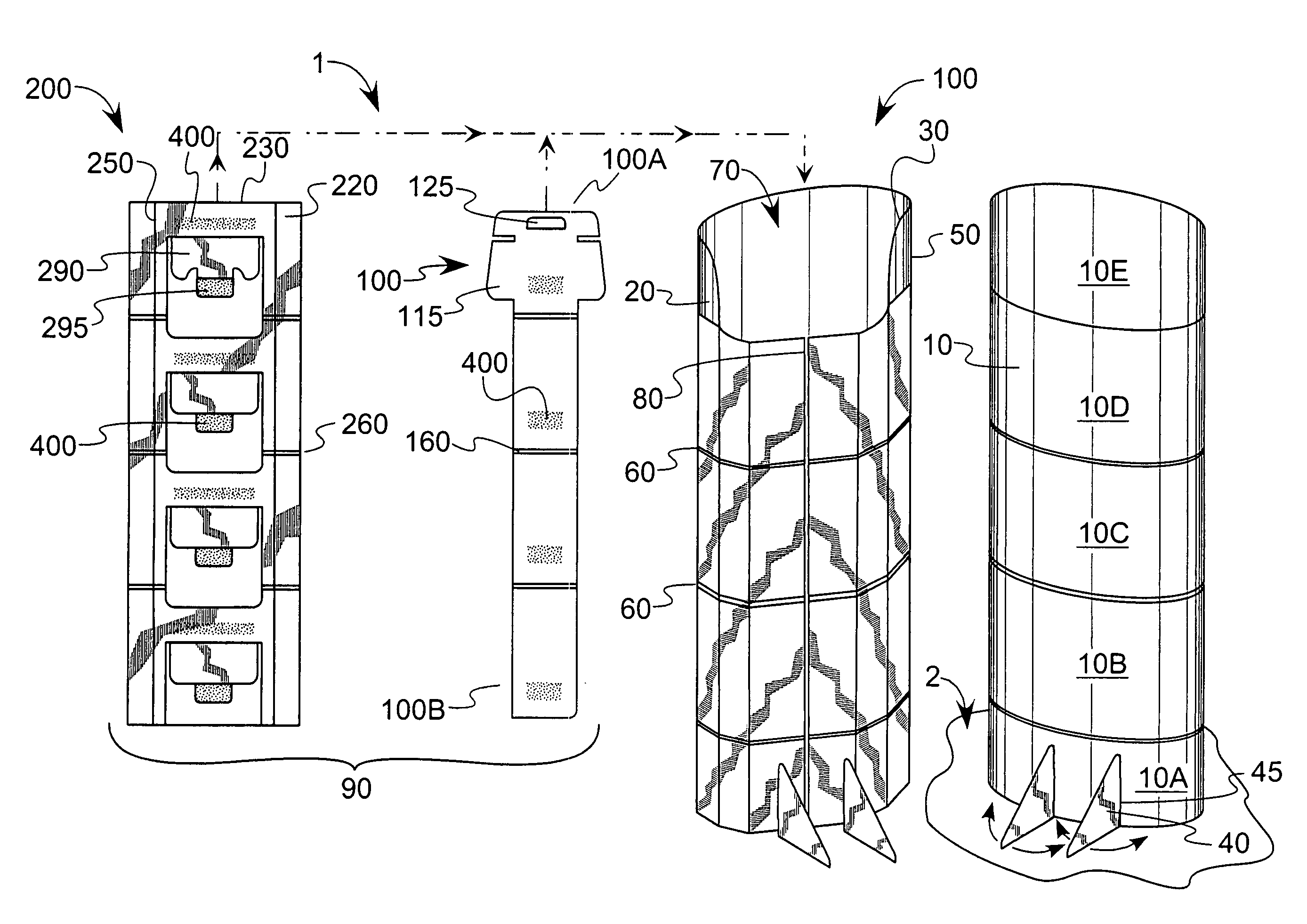
[0005]Optionally, the front panel, back panel and biasing spinal member are made of foldable paperboard, examples of which include cardboard and corrugated paper products. In addition, the front and back panels may each be subdivided into numerous panel sections, where longitudinally-spaced, horizontally extending fold lines can be used to define the various sections. Preferably, each of the fold lines in the front panel is substantially aligned with a corresponding fold line in the back panel so that, when the display is in the first position, the various panel sections can be folded over one another. This allows the display to assume a relatively compact, substantially two-dimensional shape that facilitates storage, transport or the like. In the present context, the terms “substantially two-dimensional” or “generally two-dimensional” are meant to represent the display in its folded-up shape, where the front and back panels are in a close, collapsed relation to one another, while the terms “substantially three-dimensional” or “generally three-dimensional” are meant to represent the display in its expanded shape. It will be appreciated that even though the substantially (or generally) two-dimensional shape has a three dimensional component, its small thickness dimension relative to that of the expanded (i.e., “three-dimensional”) shape makes such terminology amply descriptive of the display configuration. As with the panels, the spinal member includes a plurality of longitudinally-spaced, horizontally extending fold lines located such that they are longitudinally aligned with the aforementioned fold lines that define the panel sections. This means that the substantially planar spinal member does not appreciably hamper the ability of the display to be folded into the substantially two-dimensional storage shape. Preferably, adhesive is used to couple the spinal member to the inner surfaces of one or both of the front and back panels. The coupling (whether by adhesive, fastener or other method) is such that upon movement of the spinal member relative to the front and back panels, the cooperative bias causes the display to change from one of the first or second positions to the other of the first or second positions. In yet another option, the spinal member is adhesively coupled to at least a majority of the panel sections to promote cooperative movement among as many of the panel sections as possible. In one preferred embodiment, the front and back panels together define a unitary (i.e., one-piece) construction. The placement of the front and back panels is such that a hollow chamber is formed between them. This hollow chamber is configured to conceal a substantial majority of the spinal member from outside view, thereby both improving the aesthetics of the display in its second position and permitting both the front and back panels to accept displayable indicia thereon, thus improving the effectiveness of the display.
[0006]In yet another option, the spinal member is made up of a first element configured as a pull tab and a second element cooperative with the pull tab. The second element includes a hinged spacer, a hinged affixing tab coupled to the spacer and a panel-engaging surface coupled to at least one of the display front or back panels. In one configuration, the panel-engaging surface is adhesively affixed to an inner surface of the back panel. The affixing tab can be coupled via adhesive to the first element such that at least the spacer is rotatably responsive to translational (i.e., linear, or back-and-forth) movement of the first element to effect the change between the first and second positions. In this way, the pulling or pushing movement of the pull tab along one linear dimension causes the spacer to rotate. The spacer, by virtue of its position relative to at least one of the front or back panels, pushes or pulls the corresponding front or back panel in a dimensional substantially orthogonal to the translational movement of the pull tab to effect the substantially two-dimensional or three-dimensional profile of the respective first or second position of the panels. The display may further include a foot support coupled to a lower end of the front and back panels. The foot support can be placed within one or both of the panels such that it is substantially coplanar with the panels in the first position, yet extends out in a substantially orthogonal direction to the surface of the panel from which it extends in the second position, thereby increasing the stability of the as-erected display. In one form, the foot support is integrally formed with the spinal member.
[0011]Optionally, the step of configuring the display further comprises placing a plurality of longitudinally-spaced, horizontally extending fold lines in the front and back panels such that each of the fold lines in the front panel is substantially aligned with a corresponding fold line in the back panel to define a plurality of panel sections in the display. These panel sections can be folded over one another to define a relatively compact (including substantially two-dimensional) shape to facilitate transport or storage. An additional step can include moving the first end substantially vertically upward relative to the second end such that the panel sections become longitudinally unfolded and the display assumes an extended length. As with the previous embodiment, the spinal member includes a first element, configured as a pull tab, and a second element comprising a panel-engaging surface coupled to at least one of the front or back panels. The panel-engaging surface is made up of a hinged spacer and a hinged affixing tab coupled to the spacer in a manner previously discussed. Also as previously discussed, the front and back panels can be formed from a unitary piece of material, such as foldable paperboard, plastic or the like.

Problems solved by technology

While such displays are effective vehicles for conveying a desired message, their physical dimensions (often measuring over two feet wide by more than five feet tall) make them unwieldy and expensive to transport.
The foldable displays have certain drawbacks, despite offering additional flexibility over their nonfoldable counterparts.
The complex construction of the articulating parts of some displays are such that skilled assemblers are required, sometimes in teams of two or more.
In either case, such complexity increases the cost associated with the display.
In addition, many such displays employ numerous discrete parts that can become separated from the displays, making effective display construction more complicated.
Such structure can detract from the appearance of the display, especially where the display is situated such that people can see both the front and rear surfaces.
Furthermore, such structure takes up additional floor space.

Method used


Image

  • Stand-up display
  • Stand-up display
  • Stand-up display

Examples


Embodiment Construction

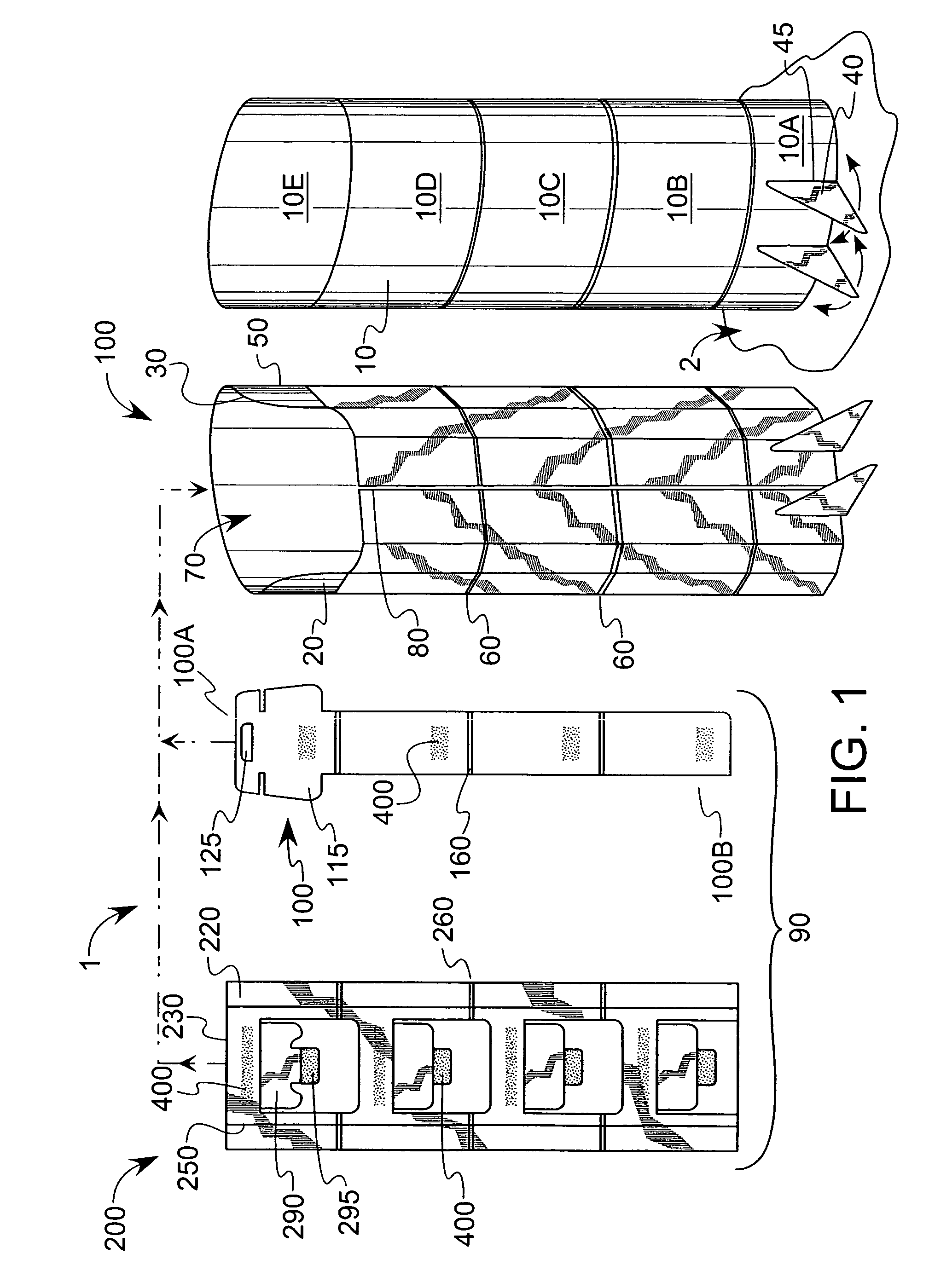
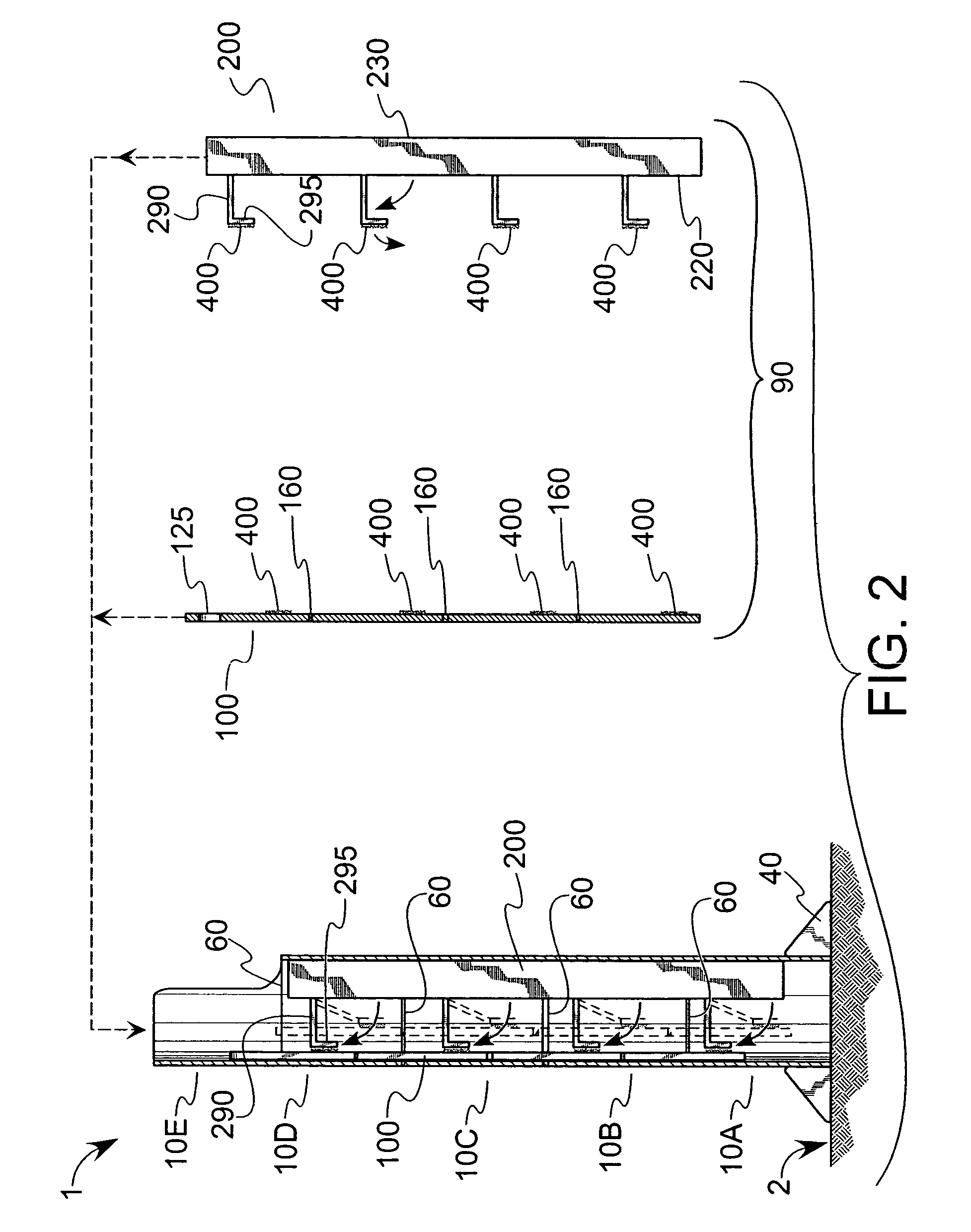
[0021]Referring first to FIGS. 1 and 2, front and side views respectively of an embodiment of the invention are shown, where a stand-up display 1 includes a front panel 10, a back panel 30 and an internal spinal member 90. During periods of use (i.e., display), optional feet 40 can be provided, extending in a generally horizontal direction from front and back panels 10, 30 to stabilize display 1 further. Although the display 1 is configured for free-standing operation without the need for the feet 40, there are situations where the use of feet 40 may be beneficial. For example, in areas where display 1 could be exposed to significant airflow (such as adjacent a heating, ventilating and air conditioning (HVAC) duct, or near a door or window), feet 40 can provide additional resistance to tipping. Longitudinal fold lines 50 are included to give rear panels 30 a faceted structure 20, while transverse (longitudinally-spaced) fold lines 60 are formed in the front, side and back panels to ...


PUM


Abstract

A display that can be expanded from a collapsed position for storage and transport to an expanded position for free-standing operation and use. A spinal member is disposed between front and back panels such that in the collapsed position, the spinal member maintains the two panels substantially adjacent one another in a generally two-dimensional shape. Upon movement of at least a portion of the spinal member relative to the panels, parts of the spinal member bias the panels apart from one another to form an expanded, three-dimensional shape. This shape provides a sufficient footprint of the display relative to its height that the display can be free-standing. The cooperative relationship between the spinal member and the panels is such that no rubber bands or related elastic devices are required to maintain the display in the expanded position.

Description

BACKGROUND OF THE INVENTION[0001]This invention relates generally to a stand-up display used for advertising and related retail functions, and more particularly to such a display that expands (i.e., pops out) from a generally planar two-dimensional shape into a three-dimensional shape with a minimal amount of human intervention.[0002]The use of stand-up displays is commonplace in the modern retail environment. In such devices, a generally portable, lightweight display is placed to attract consumer attention to a particular good or service. Visual attributes, such as life-size pictures of a celebrity endorser or the like, entice a would-be consumer to consider purchasing the good or service advertised thereon. Similarly, such displays may also be used for public service or related non-commercial information. While such displays are effective vehicles for conveying a desired message, their physical dimensions (often measuring over two feet wide by more than five feet tall) make them u...

Claims


Application Information

Patent Timeline
IPC IPC(8): G09F15/00
CPCG09F1/06G09F15/00G09F1/065
Inventor BOENS, GARYKERTH, MICHAEL S.RECKERS, JANET
Owner INNOMARK COMM
Learn More