Mapping fracture dimensions

a fracture and dimension technology, applied in the field of hydraulic fractures, can solve the problems of difficult use of methods, no direct methods of measuring the dimensions of hydraulic fractures, and analysis that verges on conjectur

Active Publication Date: 2006-11-14
SCHLUMBERGER TECH CORP
View PDF13 Cites 89 Cited by
  • Summary
  • Abstract
  • Description
  • Claims
  • Application Information

AI Technical Summary

Problems solved by technology

However, there are currently no direct methods of measuring the dimensions of a hydraulic fracture.
The three methods currently used, pressure analysis, tiltmeter observational analysis, and microseismic monitoring of hydraulic fracture growth all require de-convolution of the acquired data for the fracture geometry to be inferred through the use of models—which is highly dependent on key assumptions—and often the results of these analyses verge on conjecture.
All these methods use indirect measurements and are difficult to use except for post-job analysis rather than real-time evaluation and optimization of the hydraulic treatment.
Moreover, these methods provide little information as to the actual shape of the propped fracture.

Method used


Image

  • Mapping fracture dimensions
  • Mapping fracture dimensions
  • Mapping fracture dimensions

Examples


Embodiment Construction

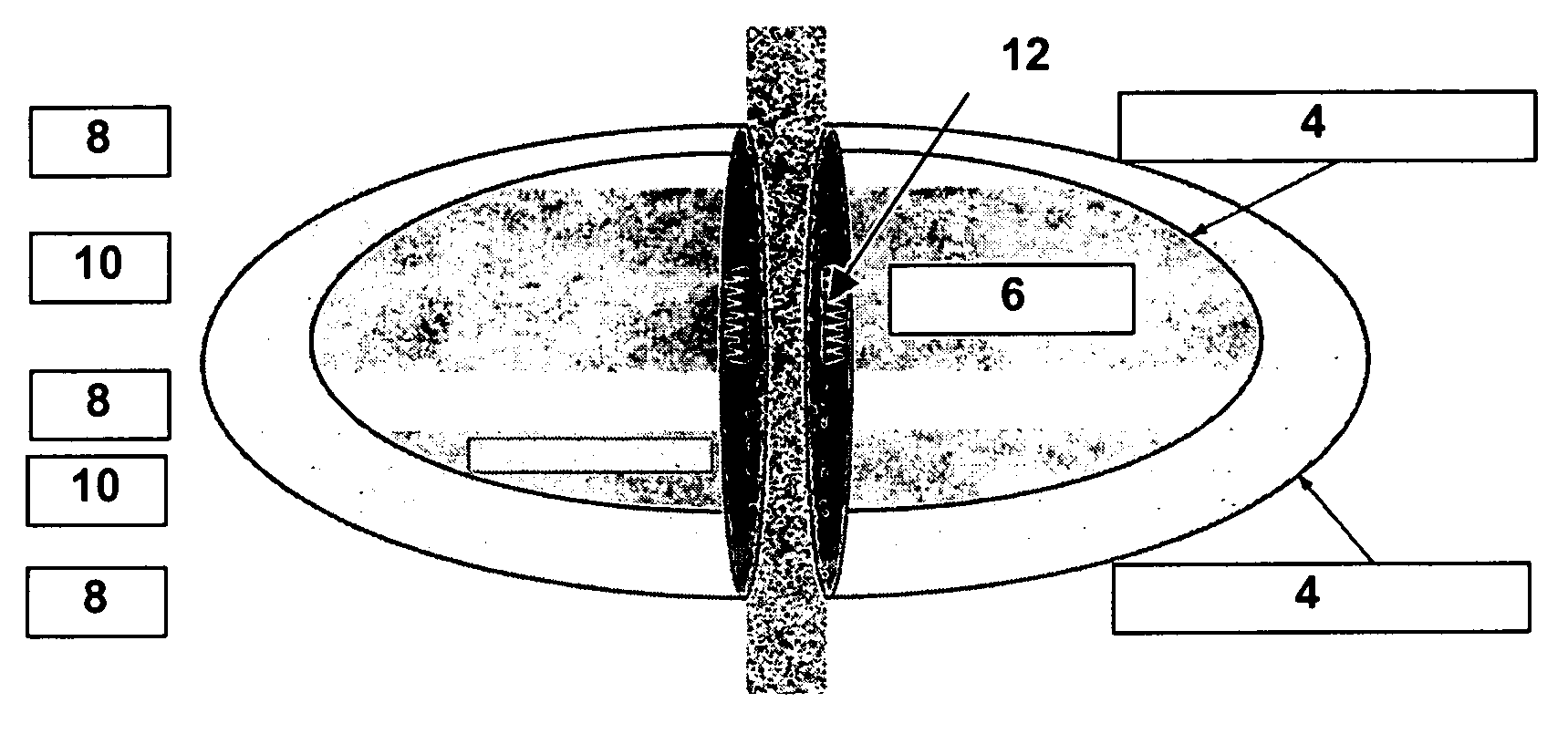
[0016]As illustrated in FIG. 1, there are three basic types of geometries one is interested in when monitoring a hydraulic fracturing treatment: that of the created fracture, where one looks for the boundary of the rock cracked open [2] during the treatment; that of the propped fracture, where one looks for the boundary of the proppant pack [4] after the fracture has closed, and that of the effective fracture, where one looks for the boundary of the fracture [6] as perceived by the reservoir and wellbore. Typically, the length and height of the effective fracture is less than that of the propped fracture, which itself is less than that of the created fracture. As one example, the reservoir in FIG. 1 contains non-pay strata [8] and pay strata [10], the perforations are at [12], and the effective fracture is the propped fracture region of the perforated pay stratum. The most desirable geometry to know is that of the effective fracture, followed by that of the propped fracture, followe...


PUM


Abstract

Hydraulic fracture dimensions and, optionally, fracture closure pressure and time are determined by adding particulate matter that discharges to create an acoustic signal to the proppant, allowing the particulate matter to discharge, and detecting the acoustic signal with geophones or accelerometers. The particulate matter may be spheres or fibers. The discharge may be explosion, implosion, detonation, or rapid combustion or ignition. The discharge may be triggered by fracture closure or by chemical reaction.

Description

CROSS-REFERENCE TO RELATED APPLICATION[0001]This application claims the benefit of U.S. Provisional Patent Application No. 60 / 463,868, filed on Apr. 18, 2003.TECHNICAL FIELD OF THE INVENTION [0002]This invention relates generally to the art of hydraulic fracturing in subterranean formations and more particularly to a method and means for assessing hydraulic fracture geometry during or after hydraulic fracturing.BACKGROUND OF THE INVENTION[0003]Hydraulic fracturing is a primary tool for improving well productivity by placing or extending channels from the wellbore to the reservoir. This operation is essentially performed by hydraulically injecting a fracturing fluid into a wellbore penetrating a subterranean formation and forcing the fracturing fluid against the formation strata by pressure. The formation strata or rock is forced to crack, creating or enlarging one or more fractures. Proppant is placed in the fracture to prevent the fracture from closing and thus the fracture provide...

Claims


Application Information

Patent Timeline
Patent Type & Authority Patents(United States)
IPC IPC(8): E21B43/267E21B43/263E21B43/26E21B47/00
CPCE21B47/00E21B43/267
Inventor WILLBERG, DEANDESROCHES, JEANBABOUR, KAMALGZARA, KAISBESSON, CHRISTIAN
Owner SCHLUMBERGER TECH CORP
Why Eureka
Try Eureka