Convertible

a convertible and convertible technology, applied in the field of convertibles, can solve the problems of wasting a lot of time, unable to open the roof from the open position, and high cost of the mechanism, so as to improve the ability to open the convertible roo

Inactive Publication Date: 2006-11-14
VALMET AUTOMOTIVE
View PDF15 Cites 19 Cited by
  • Summary
  • Abstract
  • Description
  • Claims
  • Application Information

AI Technical Summary

Benefits of technology

[0005]The goal of the invention is to improve the ability to open the roof of a convertible with rigid roof parts and a sunroof.
[0006]In accordance with the invention, a large partial opening of the roof during driving is also made possible by the plate member of the upper roof part. This plate member acts as a sunroof. Due to the fact that the sunroof lies parallel to the rear window in the open position, almost the entire region between the windshield frame and the rear roof part can be freed in this open position. Visibility to the rear is ensured by the transparency of the plate member. The lowering mechanism of the roof to its full opening is speeded up, since the sunroof, at least in its open position, in which it is kept parallel to the rear window, can be let down simultaneously (rather than successively) with the opening rear roof part.
[0009]A pivot connection of the middle section, which encloses the rear window, on both the automobile body and the upper roof part makes it possible for the middle section enclosing the rear window to act as a pivot link. The pivot joint between the middle section and the upper roof part can be elevated in such a way that the plate member is displaced over the rear roof part, and in the process the sunroof can be held in the elevated joint. This increases head clearance and reduces the risk of injury by parts situated in this region.
[0010]In particular, if both the main posts and the middle section can act as pivot links between the automobile body and the upper roof part, a pair of links is already formed on each side of the vehicle, which makes it possible to realize advantageous roof lowering kinematics. Due to the individual swivelability of the middle section, on the one hand, and of the lateral main posts, on the other hand, the roof lowering movement can be adapted to the space conditions in the automobile body, since in the lowered position, the specified parts can be spaced apart from one another, and due to an elevated position of the middle section, additional trunk space can be obtained.

Problems solved by technology

A mechanism for this is expensive.
The opening of the roof into the open position and the closing of the roof from the open position take a great deal of time.

Method used


Image

  • Convertible
  • Convertible
  • Convertible

Examples


Embodiment Construction

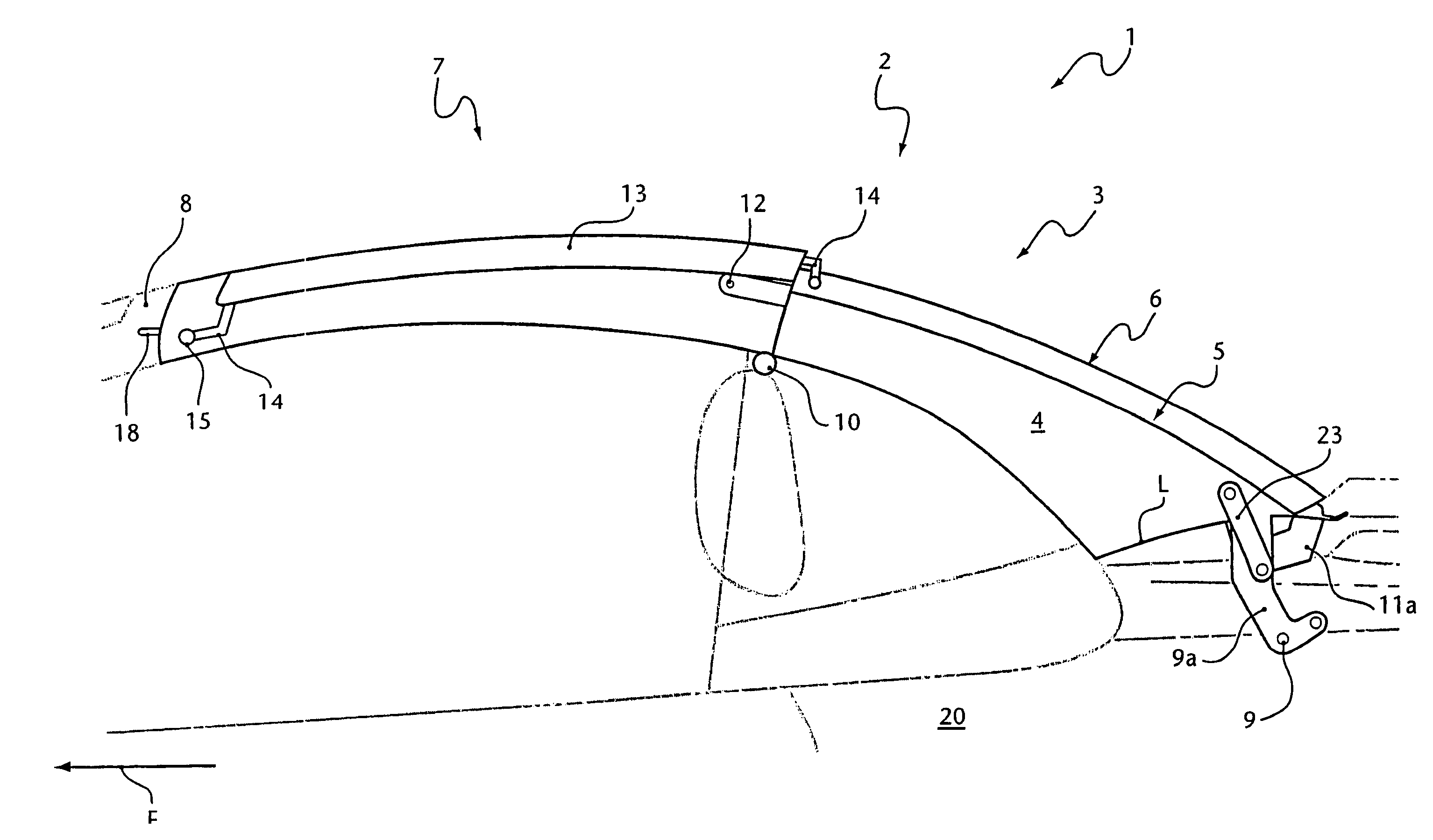
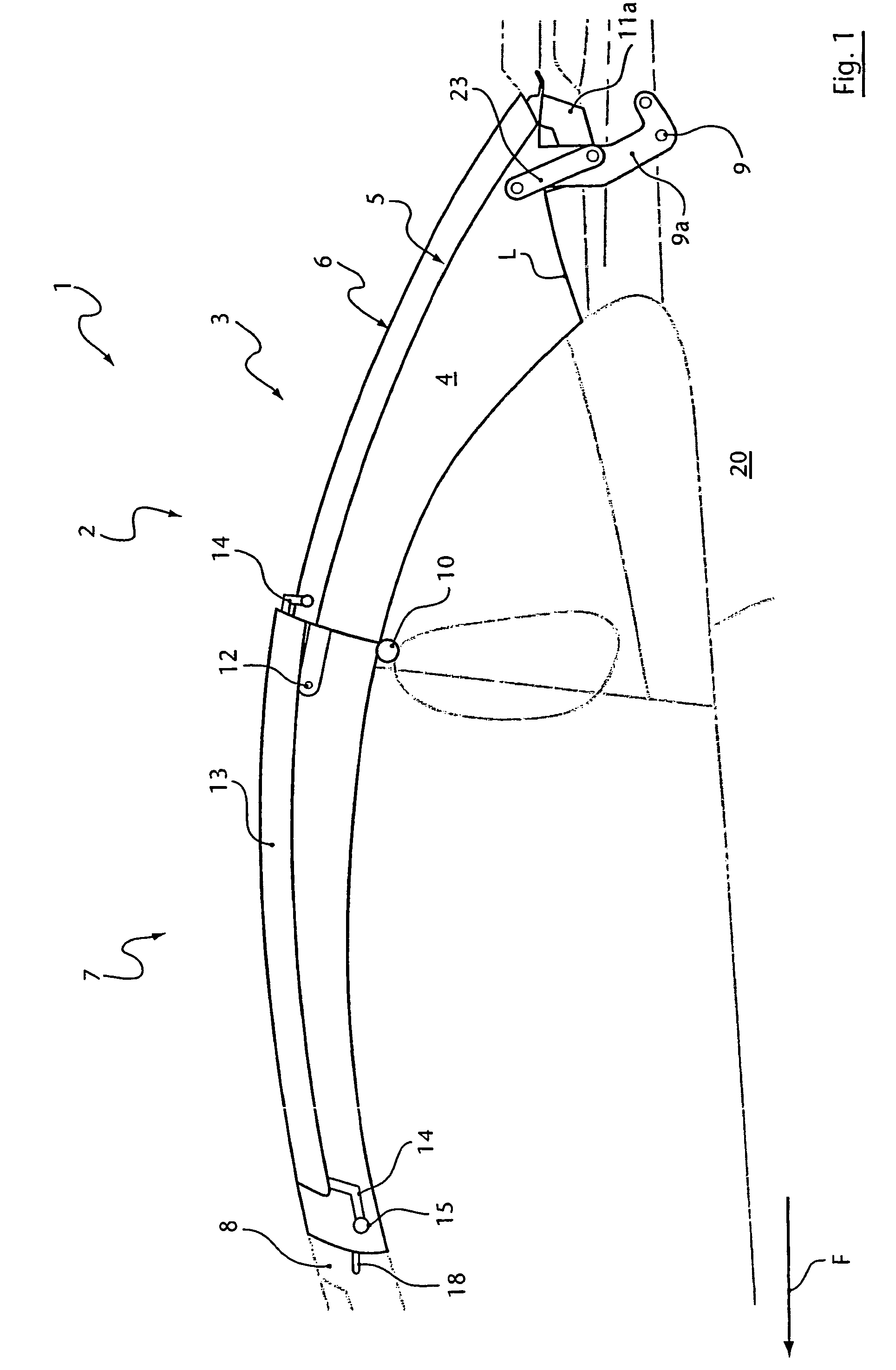
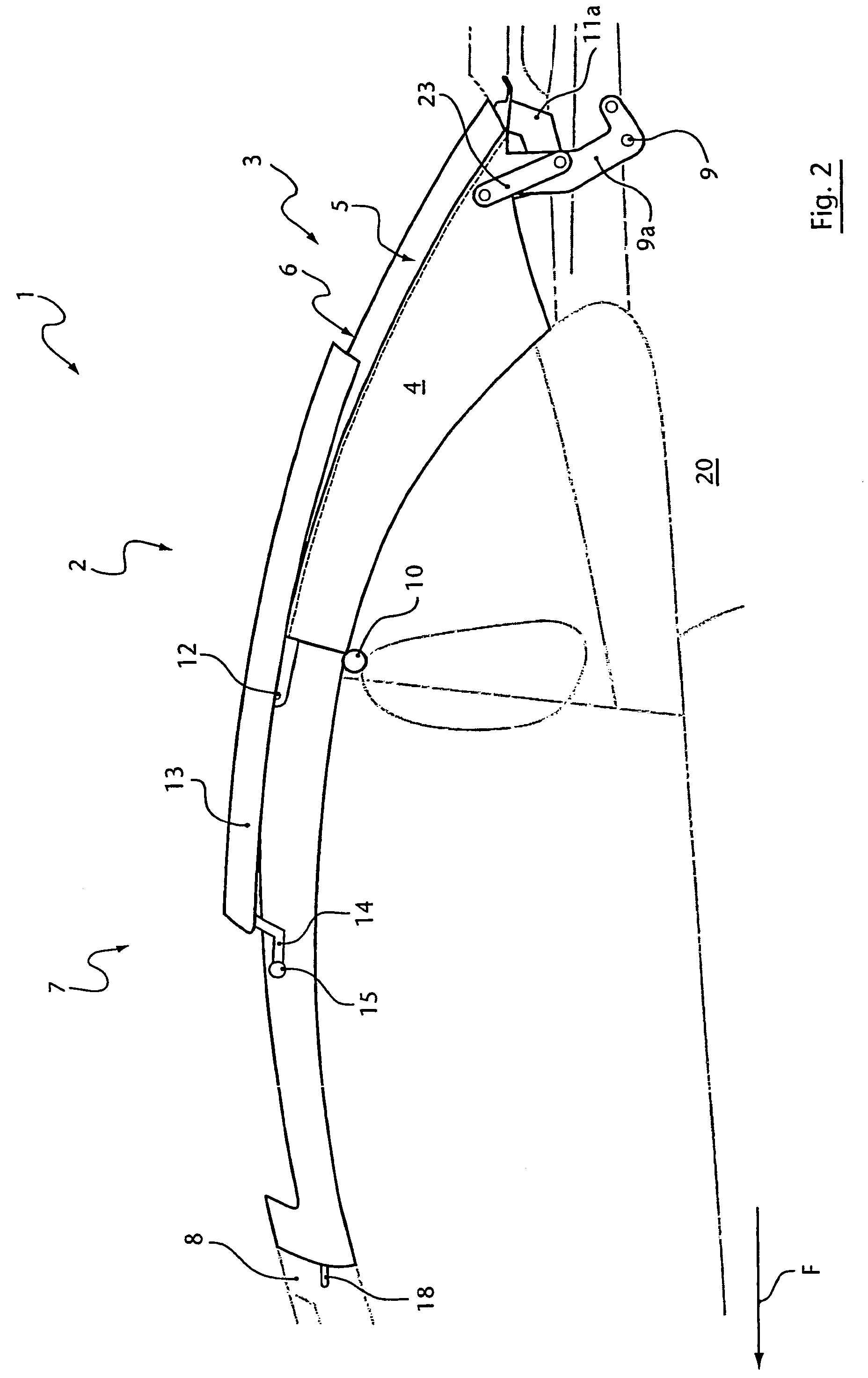
[0033]The roof 2 according to the first embodiment comprises a rear roof part 3, i.e., a roof part that is located at the rear relative to the direction of travel F, with two lateral main posts 4 and a middle section 5 located between them. The middle section encloses or is essentially formed by a flexible or, especially, rigid rear window 6, which can be made, for example, of plastic or, advantageously, glass. Both the main posts 4 and the middle section 5 are rigid and therefore can transmit torques. The main posts 4 and a possible frame 5a of the middle section 5 can be made, for example, of steel, a light metal, a metallic foam material, or plastic. It is also possible for the main posts 4 to be transparent. Moreover, the main posts 4 can be supported by frame parts.

[0034]In addition, the roof 2 comprises an upper roof part 7, which, in the closed state, is arranged in front of the rear roof part 3 in the direction of travel F of the vehicle. In the illustrated embodiment with a...


PUM


Abstract

A convertible having a roof is provided with stiff parts, at least one rear roof part, and an upper roof part, which is mounted in front of the rear roof part relative to the direction of travel in the closed state and is located above a passenger area. The upper roof part of the convertible encompasses an at least substantially transparent plate member which can be displaced counter to the direction of travel like a sliding roof; is held parallel to a rear window that is embraced by the rear roof part in the open position thereof; and can be moved along with the roof in the parallel position in order to be opened and closed.

Description

BACKGROUND OF THE INVENTION[0001]1. Field of the Invention[0002]The invention concerns a convertible.[0003]2. Description of the Related Art[0004]DE 42 03 228 C2 describes a convertible roof with a rear roof part that comprises a rear window and two lateral frame parts arranged in front of the rear roof part in the direction of travel of the vehicle. A front roof part that can be moved longitudinally relative to the two lateral frames is guided on these frames. This front roof part can be moved like a sunroof in the lateral guides, and it remains completely in the guides even in its open position. This limits the size of the roof opening formed by the sunroof opening. To allow the roof to be lowered further, the rear roof part is first swung down; only then can the upper roof part that encloses the sunroof open and rest on the rear roof part. A mechanism for this is expensive. This requires at least one additional support of the lateral frame parts relative to the automobile body, h...

Claims


Application Information

Patent Timeline
Patent Type & Authority Patents(United States)
IPC IPC(8): B60J7/14B60J7/02
CPCB60J1/1823B60J7/028B60J7/145
Inventor RUSSKE, KLAUS
Owner VALMET AUTOMOTIVE
Why Eureka
Try Eureka