
Method of adjusting multiple light sources to compensate for variation in light output that occurs with time

a technology of light output and multiple light sources, applied in the field of lighting equipment, can solve the problems of poor color rendering index over most of the range, difficulty in providing a uniform color of light throughout the interior space, and difficulty in prior lighting systems to create whi

Active Publication Date: 2006-11-14
BE AEROSPACE INCORPORATED +1
View PDF8 Cites 161 Cited by
  • Summary
  • Abstract
  • Description
  • Claims
  • Application Information

AI Technical Summary

Benefits of technology

The patent describes a lighting apparatus that produces different colored light to create a resultant color. To ensure the desired resultant color is produced, the method includes adjusting the operation of each light source by sensing the characteristic of the light produced by each light source and comparing it to a reference value. The operation of the light source is adjusted until its sensed value matches the reference value. This allows for individual control of each light source, resulting in better control over the overall color of the lighting apparatus.

Problems solved by technology

However, it is difficult with prior lighting systems to create white light that adheres to the Planckian radiator curve on the CIE chromaticity chart and has a CRI greater than 80.
Although this type of lighting apparatus can replicate the Planckian radiator over a range in the visible spectrum of light, it has a poor Color Rendering Index over most of that range.
Thus it is difficult to provide a uniform color of light throughout the interior space.

Method used


Image

  • Method of adjusting multiple light sources to compensate for variation in light output that occurs with time
  • Method of adjusting multiple light sources to compensate for variation in light output that occurs with time
  • Method of adjusting multiple light sources to compensate for variation in light output that occurs with time

Examples


Embodiment Construction

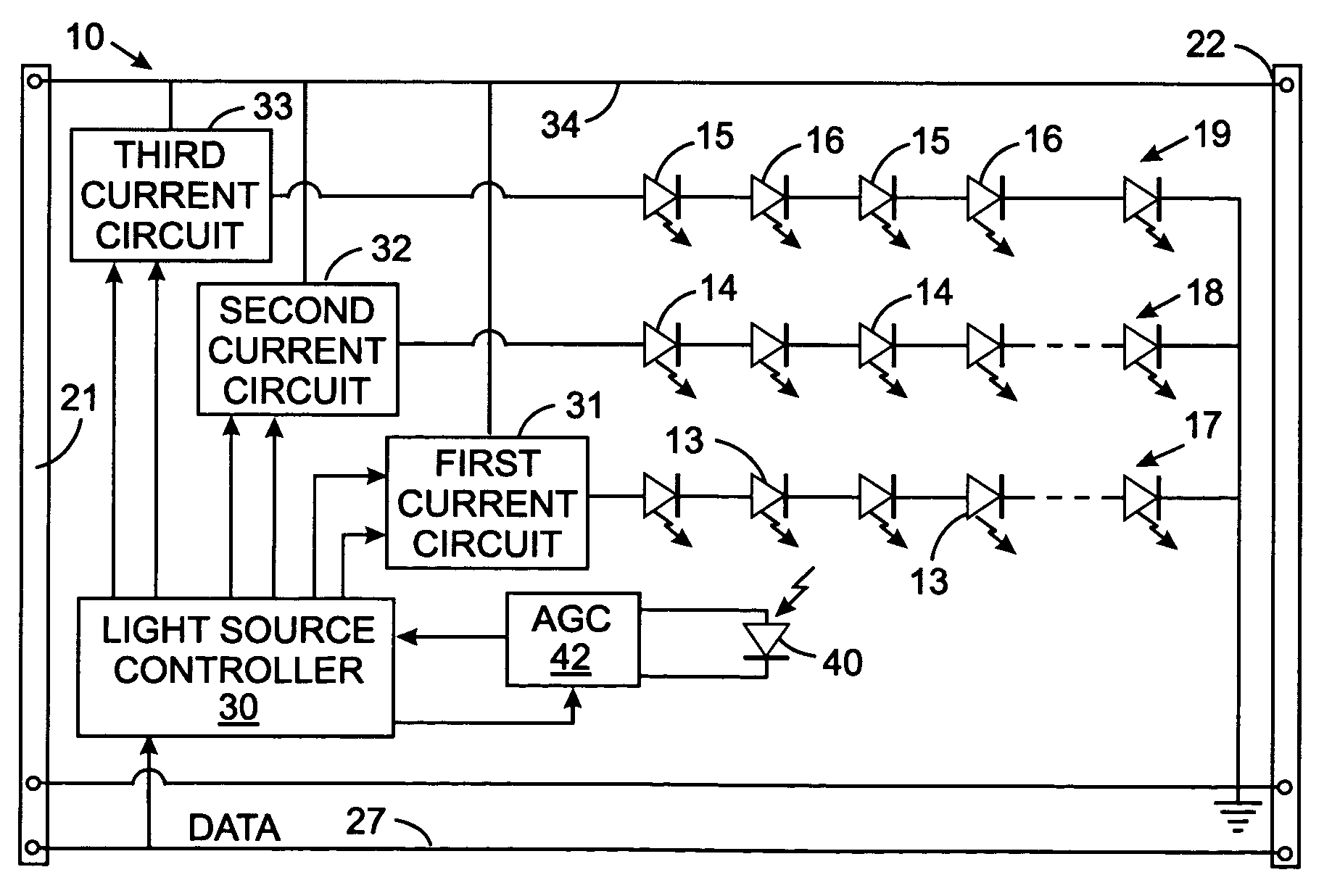
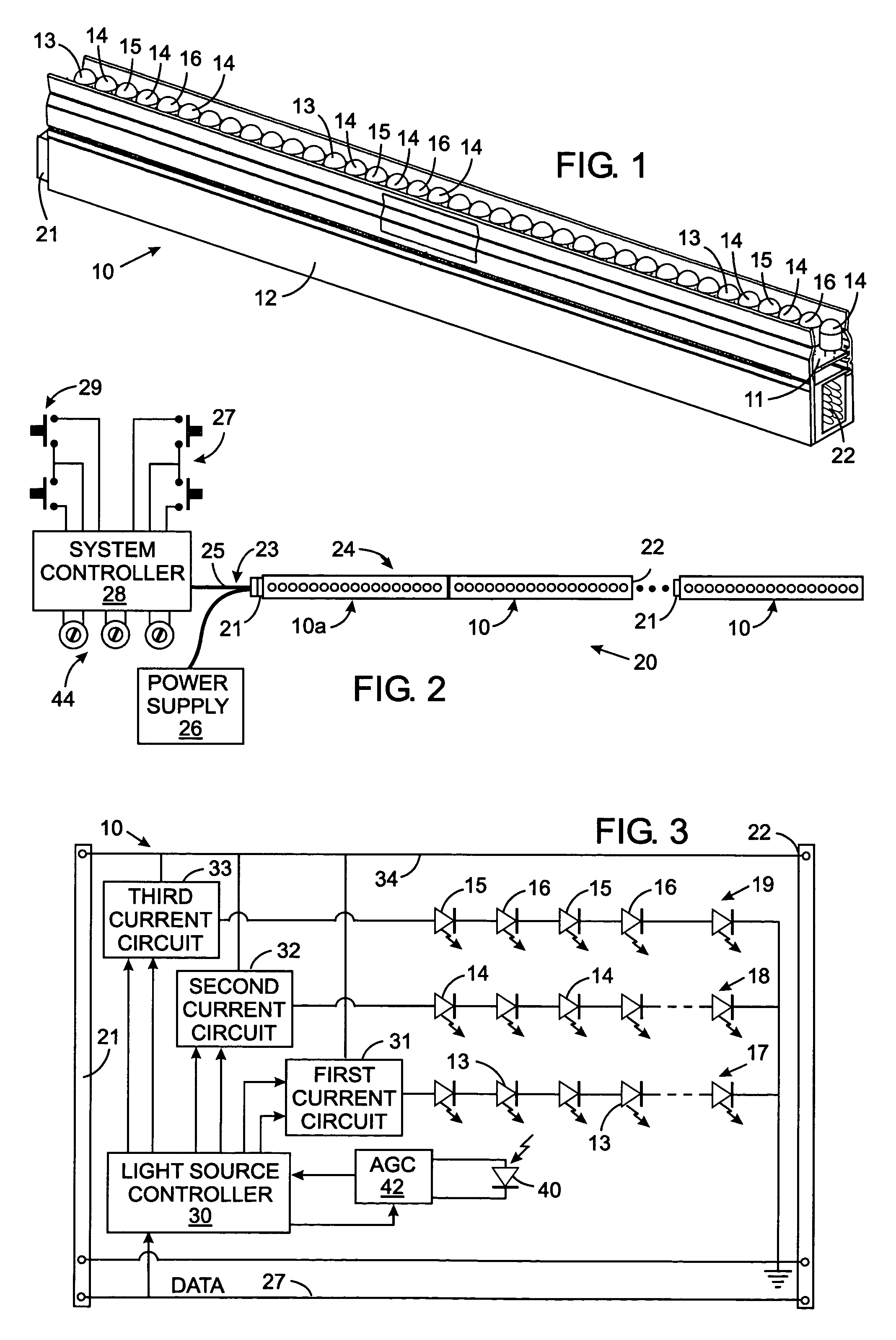
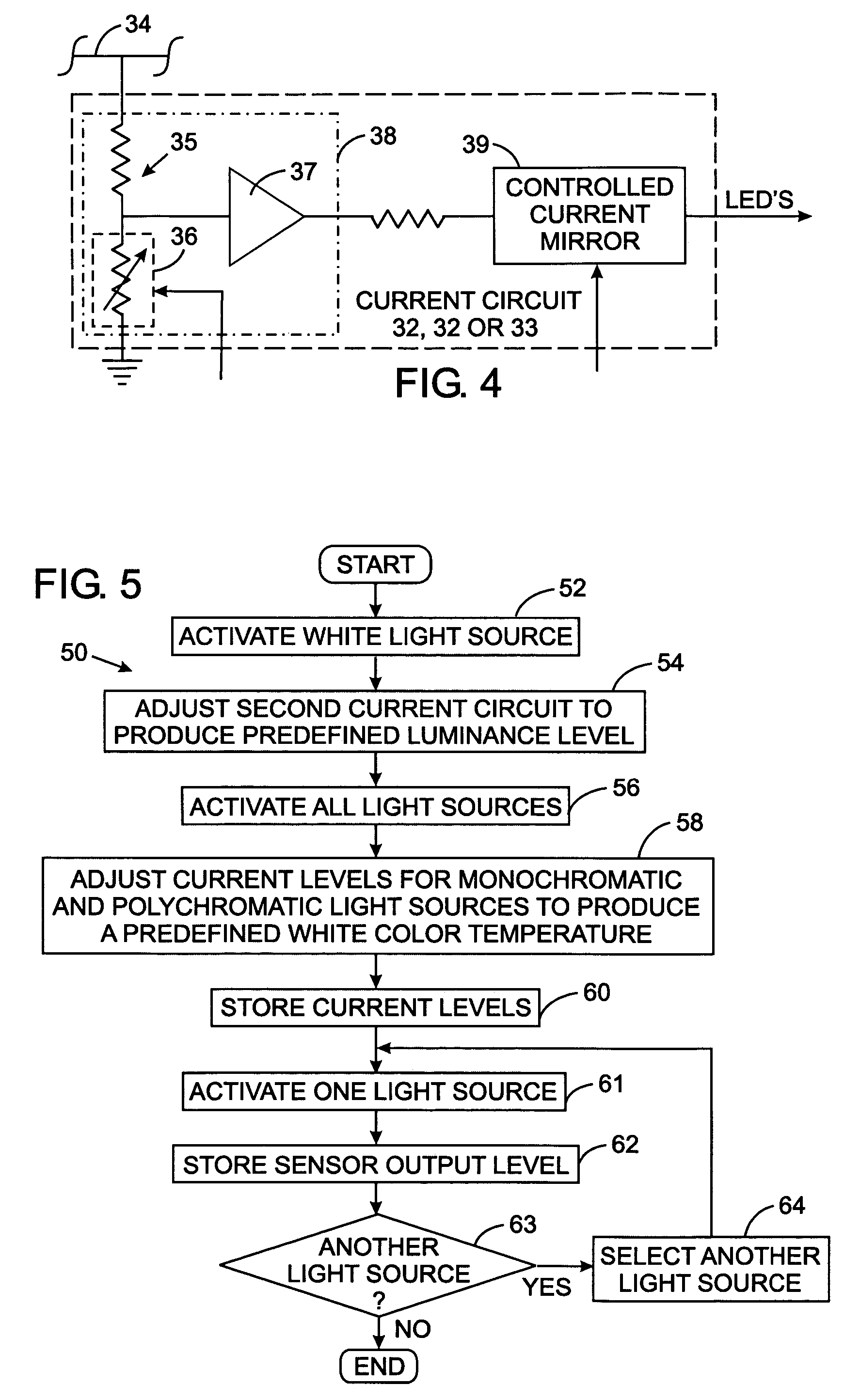
[0024]With initial reference to FIG. 1, a lighting strip 10 includes a housing 12 in with a U-shaped channel which supports longitudinal edges of a printed circuit board 11. A plurality of light emitting diodes (LED's) 13, 14, 15 and 16 are mounted along a row that extends longitudinally on the printed circuit board 11. The first type of LED's 13, which preferably emit red light, collectively form a monochromatic light source 17. As used herein a monochromatic light source emits light in which 90% of the energy is concentrated within a spectral wavelength width of a few angstroms. The second type of LED's 14 emit white light and create a broad spectrum light source 18. For example, each second type of LED 14 emits blue light that strikes a phosphor coating which produces white light of a correlated color temperature greater than 6500° Kelvin. The third type of LED's 15 preferably emits amber light and fourth type of LED's 16 preferably emits green light. The third and fourth types L...


PUM


Abstract

A feedback method on occasion independently senses a characteristic of light produced by each of several light sources in a lighting apparatus. The sensed value of that characteristic is compared to a reference value for the respective light source and that light source's operation is adjusted accordingly. This method has particular application in a lighting apparatus that produces different lighting effects by varying the intensity of different colors of light produced by the various light sources. The feedback method compensates for light emission variation as the sources age, thus ensuring that the lighting apparatus continues to produce the desired lighting effects. This enables multiple lighting apparatus in an area to be calibrated to the same standard so that uniform illumination is provided.

Description

CROSS-REFERENCE TO RELATED APPLICATIONS[0001]Not ApplicableSTATEMENT REGARDING FEDERALLY SPONSORED RESEARCH OR DEVELOPMENT[0002]Not ApplicableBACKGROUND OF THE INVENTION[0003]1. Field of the Invention[0004]The present invention relates to lighting apparatus which produce white light that is variable within a predefined range of correlated color temperatures, and more particularly to such lighting apparatus that employ a plurality of light sources each emitting light of a different color which blend together to produce the white light.[0005]2. Description of the Related Art[0006]The interior spaces, such as those of buildings and vehicles, historically were illuminated by incandescent or fluorescent lighting devices. More recently lighting systems have been developed that utilize groups of a light emitting diodes (LED's). For example U.S. Pat. No. 6,158,882 describes a vehicle lighting system which employs a plurality of LED's mounted in a linear array to form a lighting strip. By va...

Claims


Application Information

Patent Timeline
Patent Type & Authority Patents(United States)
IPC IPC(8): G01J1/32
CPCH05B33/0869H05B45/22
Inventor VORNSAND, STEVEN J.HAMILTON, DOUGLAS M.
Owner BE AEROSPACE INCORPORATED
Learn More