Transflective liquid crystal display device using transflective color filter and method for making color filter

Inactive Publication Date: 2006-11-14
INNOLUX CORP
View PDF5 Cites 4 Cited by
  • Summary
  • Abstract
  • Description
  • Claims
  • Application Information

AI Technical Summary

Benefits of technology

[0017]Another object of the invention is to provide a transflective liquid crystal display device having high color purity.
[0018]A further object of the invention is to provide a method for fabricating a color filter for a transflective LCD device, in which the color filter has high color purity.

Problems solved by technology

Because the transmissive LCD device requires a back light having high brightness, it has high power consumption.
Further, the back light device cannot be used for a long time.
However, the reflective LCD device is useless when the weather is unfavorable or when the external light source is not available.

Method used


Image

  • Transflective liquid crystal display device using transflective color filter and method for making color filter
  • Transflective liquid crystal display device using transflective color filter and method for making color filter
  • Transflective liquid crystal display device using transflective color filter and method for making color filter

Examples


first embodiment

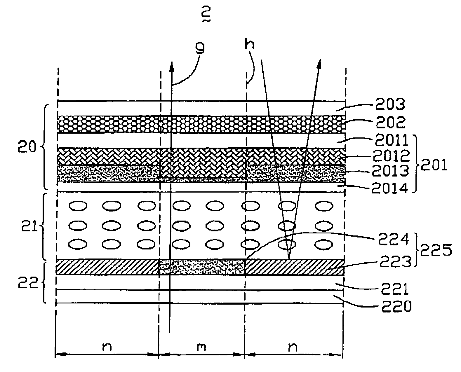
[0034]FIG. 1 illustrates part of a transflective liquid crystal display (LCD) device 2 according to the present invention. For the sake of convenience, only one sub-pixel of the transflective LCD device 2 is shown. The transflective LCD device 2 includes an upper plate 20, a lower plate 22, a liquid crystal layer 21 interposed therebetween, and a back light (not shown) disposed below the lower plate 22.

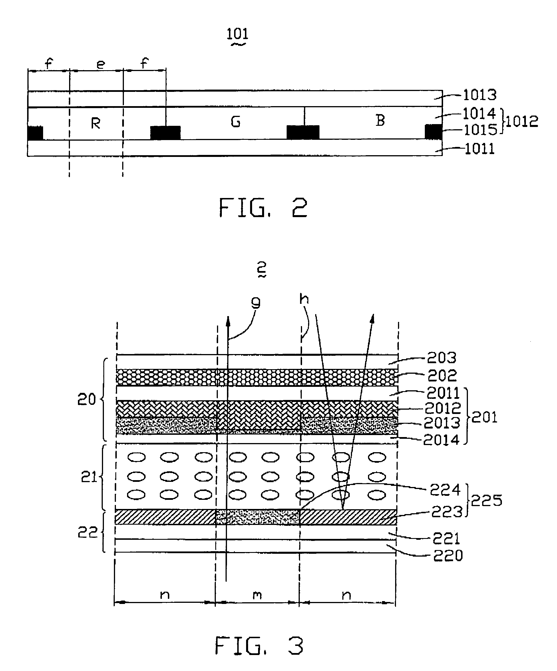
[0035]In the upper plate 20, a first color filter 201, a half wave plate 202 and an upper polarizer 203 are stacked sequentially. Referring also to FIG. 2, for the sake of convenience, just one pixel of the first color filter 201 is shown. In general, one pixel comprises three sub-pixels. The first color filter 201 includes a transparent substrate 2011, a color filter layer 2012, an upper transparent electrode layer 2013, and a transparent layer 2014. The color filter layer 2012 is formed on a bottom surface (not labeled) of the transparent substrate 2011, and includes a plurality of ...

third embodiment

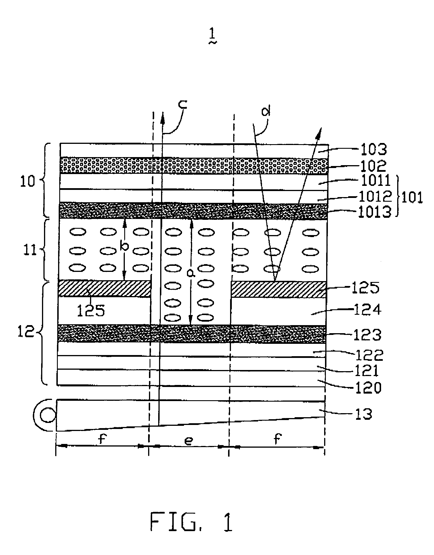
[0042]FIG. 4 shows part of a third color filter 401 of a transflective liquid crystal display device according to the present invention. For the sake of convenience, just one pixel of the third color filter 401 is shown. In general, one pixel comprises three sub-pixels. The third color filter 401 includes a transparent substrate 4011, a color filter layer 4012, an upper transparent electrode layer 4013, and a transparent layer 4014. The color filter layer 4012 is formed on a bottom surface (not labeled) of the transparent substrate 4011, and includes a plurality of color units 4015 comprising red color units “R,” green color units “G” and blue color units “B”. Each color unit 4015 comprises a first overlapping portion 4015a, a second overlapping portion 4015b, and a middle portion 4015c therebetween. The first overlapping portions 4015a of color units 4015 overlap on the second overlapping portions 4015b of contiguous color units 4015 to form a plurality of light blocking areas (not...


PUM


Abstract

A color filter (401) for a transflective liquid crystal display (LCD) includes a transparent substrate (4011), a color filter layer (4012) covering the transparent substrate, a transparent electrode (4013) covering the color filter layer, and a transparent layer (4014). The color filter layer comprises a plurality of color units (4015). Each color unit has a first overlapping portion (4015a), a second overlapping portion (4015b) and a middle portion (4015c) therebetween, and the first overlapping portions of color units are formed on second overlapping portions of contiguous color units to form a plurality of light blocking areas, the middle portion of each color unit has a first portion (r) that corresponds to a reflective mode, and a second portion (t) that corresponds to a transmissive mode. The second portion is thicker than the first portion. A transflective LCD using the color filter is also described.

Description

BACKGROUND OF THE INVENTION[0001]1. Field of the Invention[0002]The present invention relates to liquid crystal displays, and more particularly to transflective liquid crystal display devices.[0003]2. Description of the Prior Art[0004]Liquid crystal display (LCD) devices are in wide use as display devices capable of reducing the overall size, weight and thickness of electronic apparatuses in which they are employed. In general, LCD devices are divided into two categories—transmissive LCD devices and reflective LCD devices—according to whether the display uses an included or an external light source.[0005]A transmissive LCD device displays images using light from a back light device, and is usable under any ambient light conditions. Because the transmissive LCD device requires a back light having high brightness, it has high power consumption. Further, the back light device cannot be used for a long time.[0006]Unlike the transmissive LCD device, a reflective LCD device utilizes ambie...

Claims


Application Information

Patent Timeline
IPC IPC(8): G02F1/1335
CPCG02F1/133512G02F1/133555G02F1/133504
Inventor YEH, SHENG-SHIOUPANG, JIA-PANG
Owner INNOLUX CORP
Why Eureka
Try Eureka