Head positioning control method for a storage device and head positioning control device

a control method and positioning technology, applied in the direction of recording information storage, maintaining head carrier alignment, instruments, etc., can solve the problems of long settle time, affecting the friction and grease condition of the actuator bearing, and it is difficult to reduce the settle time. , to achieve the effect of shortening the seek tim

Inactive Publication Date: 2006-11-14
KK TOSHIBA
View PDF25 Cites 14 Cited by
  • Summary
  • Abstract
  • Description
  • Claims
  • Application Information

AI Technical Summary

Benefits of technology

[0021]The objective of this invention is to provide a head positioning control method and a head positioning control device for shortening the seek time.
[0022]Moreover, another objective of this invention is to provide a head positioning control method and a head positioning: control device that make it possible to more quickly and accurately estimate the steady-state bias and to reduce the settling time.
[0023]Another objective of this invention is to provide a head positioning control method and a head positioning control device that make it possible to more quickly and accurately estimate the steady-state bias and reduce the fluctuations in settling time.

Problems solved by technology

As the time required for coarse control is determined according to the distance of movement, and the maximum current value of the power amp, it is difficult to reduce this time.
First, a steady-state bias (external force) applied to the actuator influences the settling time.
These external forces also affect the friction and grease condition of the actuator bearings.
When this bias value is not corrected, the settling time becomes long.
However, in the prior art, there are the following problems. FIG. 56 shows the characteristics of the steady-state bias.
Therefore, in the prior method of using a bias table of average bias values, the shift in bias values is large.
Since this error cannot be estimated in advance, correction is not possible.
Therefore, in a feedback control system in settling control, there must be time to correct this shift in bias value, and so there is the problem of not being able to shorten the settling time.
Therefore, it takes time to correctly estimate the bias value, and so there was the problem of not being able to shorten the settling time.
(3) Furthermore, in the prior method of changing the response characteristics during settling control, the dynamic characteristics of the feedback control system are improved, however the position error increased and position offset occurred, making it impossible to shorten the settling time.
Also, since it is necessary to correct the shift in the bias value, there is the problem of not being able to shorten the settling time.
However, the track width becomes more narrow and it is not possible to ignore the effect on the velocity even when there is only small external vibration.
When the velocity is large, there is the problem that it takes time for convergence, and it is difficult for the velocity error to be restored within the target time.
For short-distance seek, it takes 1 ms or less to seek one track, for example, so there is the problem that the effect of velocity error is large, and that it is not possible to shorten the convergence time.

Method used


Image

  • Head positioning control method for a storage device and head positioning control device
  • Head positioning control method for a storage device and head positioning control device
  • Head positioning control method for a storage device and head positioning control device

Examples


Embodiment Construction

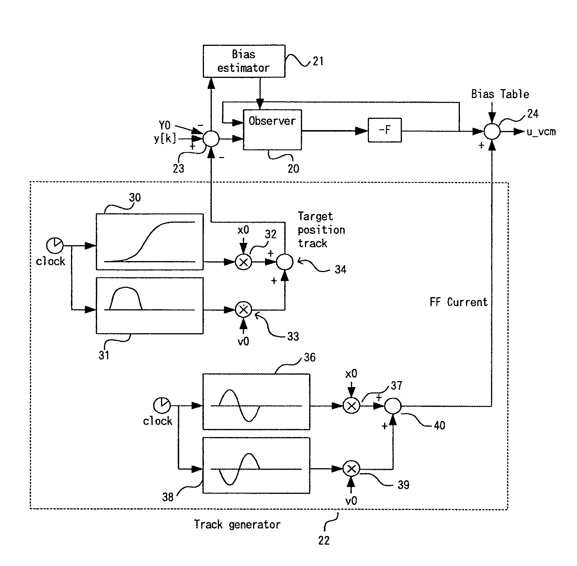
[0096]The embodiments of this invention will be explained by dividing them into the disk device, positioning control system, positioning control process, example of bias estimation, positioning control for another embodiment, positioning control for a further embodiment, trajectory generation method, example of trajectory control, and another embodiment.

Disk Device

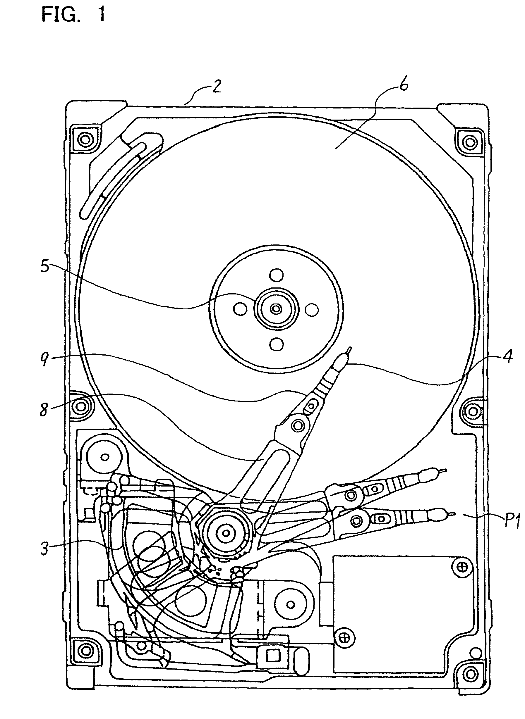
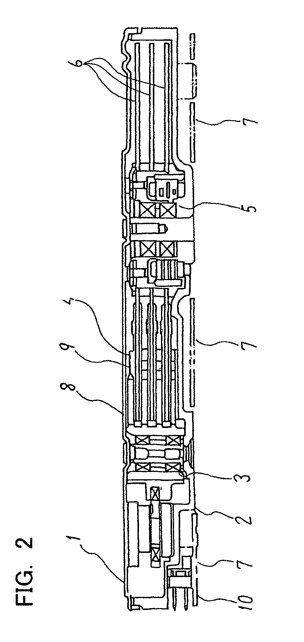
[0097]FIG. 1 is a top view of the disk device of an embodiment of the invention, and FIG. 2 is a cross-sectional view of that disk device. In this example, a hard disk drive is used as the storage device.

[0098]As shown in FIG. 1 and FIG. 2, magnetic disks 6 are such that they form storage layers on a substrate (disk plate). The size of the magnetic disks 6 is 2.5 inches, and there are three disks inside the drive. A spindle motor 5 supports and rotates the magnetic disks 6. A magnetic head 4 is located on the actuator. The actuator comprises a rotary-type VCM (voice coil motor) 3, arm 8 and flexure (suspension) 9. The magn...


PUM

PropertyMeasurementUnit
timeaaaaaaaaaa
timeaaaaaaaaaa
sizeaaaaaaaaaa

Abstract

A head positioning method and device positions a head which reads a disk-type storage medium at a specified location, and accurately estimates a bias value during settling control. A disk device includes a disk medium, a head, an actuator, and a control circuit, and settling control is performed based on a detected position after coarse control without integral compensation or bias compensation having been performed. The position of the head for a next sample is estimated, and an initial bias value is estimated from the difference between the detected position and the estimated position. This initial bias value is then used to perform settling control together with integral compensation of bias compensation. Since the accurate initial bias value at the start of settling is estimated, it is possible to reduce the time for correcting the shift in the bias during settling control, and greatly reduce the time required for settling control.

Description

[0001]This is a Divisional of parent application Ser. No. 09 / 713,578, filed Nov. 16, 2000, now U.S. Pat. No. 6,995,944.BACKGROUND OF THE INVENTION[0002]1. Field of the Invention[0003]This invention relates a head positioning control method and a head positioning control device for positioning a head at a target position of a storage medium, and particularly to a head positioning control method and a head positioning control device for reducing the seek time.[0004]2. Description of the Related Art[0005]Disk devices that have a head for reading disk-type storage medium are widely used. For example the magnetic disk drives used as a storage devices for computers comprise a magnetic disk, a spindle motor for rotating the magnetic disk, a head for reading from and writing to the magnetic disk, and a VCM actuator for positioning the head on a track of the magnetic disk. The storage density of these kinds of disk drives is rapidly increasing, as well as is the track density of the magnetic...

Claims


Application Information

Patent Timeline
Patent Type & Authority Patents(United States)
IPC IPC(8): G11B5/55G11B5/596G11B21/10G11B21/08
CPCG11B5/5534G11B5/59627
Inventor TAKAISHI, KAZUHIKOSAITO, SHUNJI
Owner KK TOSHIBA
Why Eureka
Try Eureka