System for calculating remaining capacity of energy storage device

a technology for energy storage devices and systems, applied in the field of systems for calculating the remaining capacity of energy storage devices, can solve the problems of cumulative errors, easy varying of calculated remaining capacity, and increased error

Inactive Publication Date: 2006-11-14
SUBARU CORP
View PDF12 Cites 60 Cited by
  • Summary
  • Abstract
  • Description
  • Claims
  • Application Information

AI Technical Summary

Benefits of technology

[0013]Accordingly, it is an object of the present invention to provide a system for calculating the remaining capacity of an energy storage device, which is capable of making full use of the advantages of the remaining capacity of the energy storage device obtained based on current integration and those of the remaining capacity thereof obtained based on its open circuit voltage and also capable of always obtaining the final remaining capacity with uniform accuracy.

Problems solved by technology

The first approach has an advantage in that the determination of remaining capacity is not influenced by the load fluctuation in the energy storage device caused by peak current, but has a disadvantage in that a cumulative error often occurs (particularly, the error may increase during high-load conditions).
The second approach has an advantage in that the efficiency is high so long as the open circuit voltage is estimated with accuracy but has a disadvantage in that even when load significantly changes for a short time, the calculated remaining capacity easily varies.
According to the technique disclosed in Patent Document 1, however, the accuracy with which the remaining capacity of the battery is calculated while the electric vehicle is running is not ensured.
Therefore, the technique of Patent Document 1 is of limited application.
It is difficult to apply this technique to hybrid electric vehicles in which charging and discharging are repeated.
Therefore, when this technique is applied to a hybrid electric vehicle, an abrupt change in calculated remaining capacity may adversely affect vehicle control.

Method used


Image

  • System for calculating remaining capacity of energy storage device
  • System for calculating remaining capacity of energy storage device
  • System for calculating remaining capacity of energy storage device

Examples


Embodiment Construction

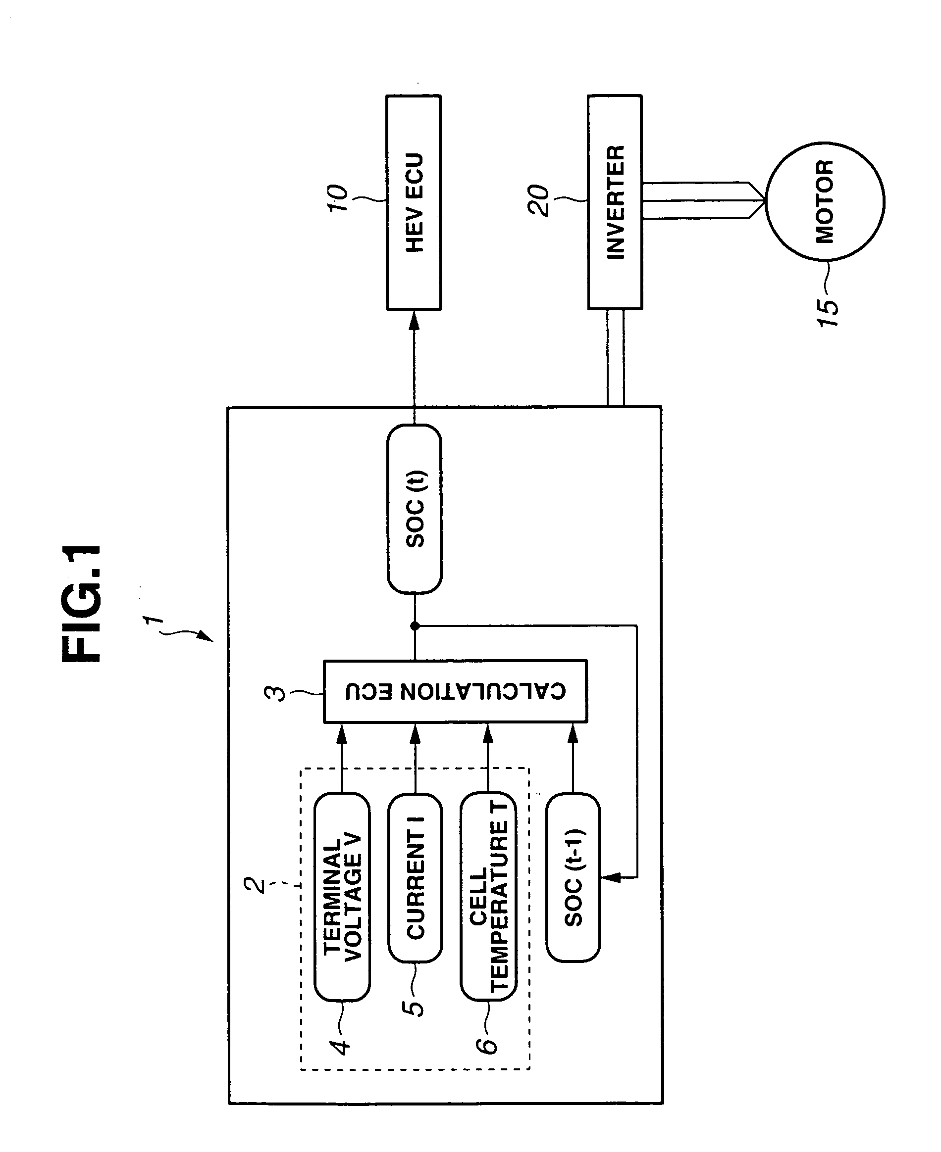
[0027]FIG. 1 shows an embodiment of the present invention. According to the present embodiment, a system for calculating the remaining capacity of an energy storage device is applied to a hybrid electric vehicle (HEV) with the combination of an engine and a motor. Referring to FIG. 1, an HEV power supply unit 1 includes; a battery 2 which serves as an energy storage device and is composed of, for example, a plurality of multi-cell battery packs connected in series; and a calculation unit (electronic control unit (ECU) for calculation) 3 for performing energy management, i.e., calculating the remaining capacity of the battery 2, controlling cooling or charging the battery 2, detecting malfunction, and performing the protecting operation upon detecting malfunction. The battery 2 and the calculation unit 3 are packaged in one casing.

[0028]In the present embodiment the description will be based on the assumption that a lithium-ion secondary battery is used as an energy storage device. T...


PUM


Abstract

The remaining capacity of a battery obtained by integrating current and that obtained from the estimated open circuit voltage of the battery are weighted with a weight which varies depending on the operating conditions of the battery as needed and the weighted remaining capacities are combined into the final remaining capacity. Thus, the disadvantages of the remaining capacity based on current integration and those of the remaining capacity based on the estimated open circuit voltage cancel each other out and the advantages of the respective remaining capacities can be fully utilized. The uniform calculation accuracy can be ensured and the final remaining capacity can always be obtained with accuracy.

Description

[0001]This application claims benefit of Japanese Application No. 2004-7376 filed on Jan. 14, 2004, the contents of which are incorporated by this reference.BACKGROUND OF THE INVENTION[0002]1. Field of the Invention[0003]The present invention relates to a system for calculating the remaining capacity of an energy storage device such as a secondary battery or an electrochemical capacitor.[0004]2. Description of the Related Art[0005]The miniaturization of energy storage devices such as secondary batteries including nickel metal hydride batteries and lithium-ion batteries, and electrochemical capacitors including electric double layer capacitors is advancing, and the increase of the energy densities thereof is also encouraged. Those energy storage devices are actively used as power sources for portable information communication devices, electric vehicles, and hybrid electric vehicles.[0006]To effectively utilize the energy storage device, grasping the accurate residual or remaining cap...

Claims


Application Information

Patent Timeline
Patent Type & Authority Patents(United States)
IPC IPC(8): G06F19/00G01R31/36H02J7/00
CPCG01R31/361G01R31/3648G01R31/3662G01R31/389G01R31/3828
Inventor ONO, MIKIO
Owner SUBARU CORP
Why Eureka
Try Eureka