Support structure of high pressure container

a technology of support structure and high pressure container, which is applied in the direction of furniture parts, washstands, containers discharging methods, etc., can solve the problem of failure to secure the cylinder

Inactive Publication Date: 2006-11-21
NISSAN MOTOR CO LTD
View PDF30 Cites 80 Cited by
  • Summary
  • Abstract
  • Description
  • Claims
  • Application Information

AI Technical Summary

Benefits of technology

[0004]An object of the present invention is to provide...

Problems solved by technology

Particularly, an outer diameter of the main body changes to ...

Method used


Image

  • Support structure of high pressure container
  • Support structure of high pressure container
  • Support structure of high pressure container

Examples


Embodiment Construction

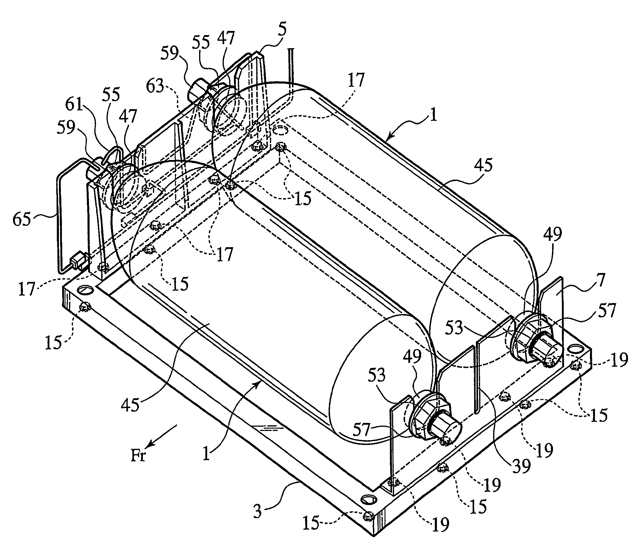
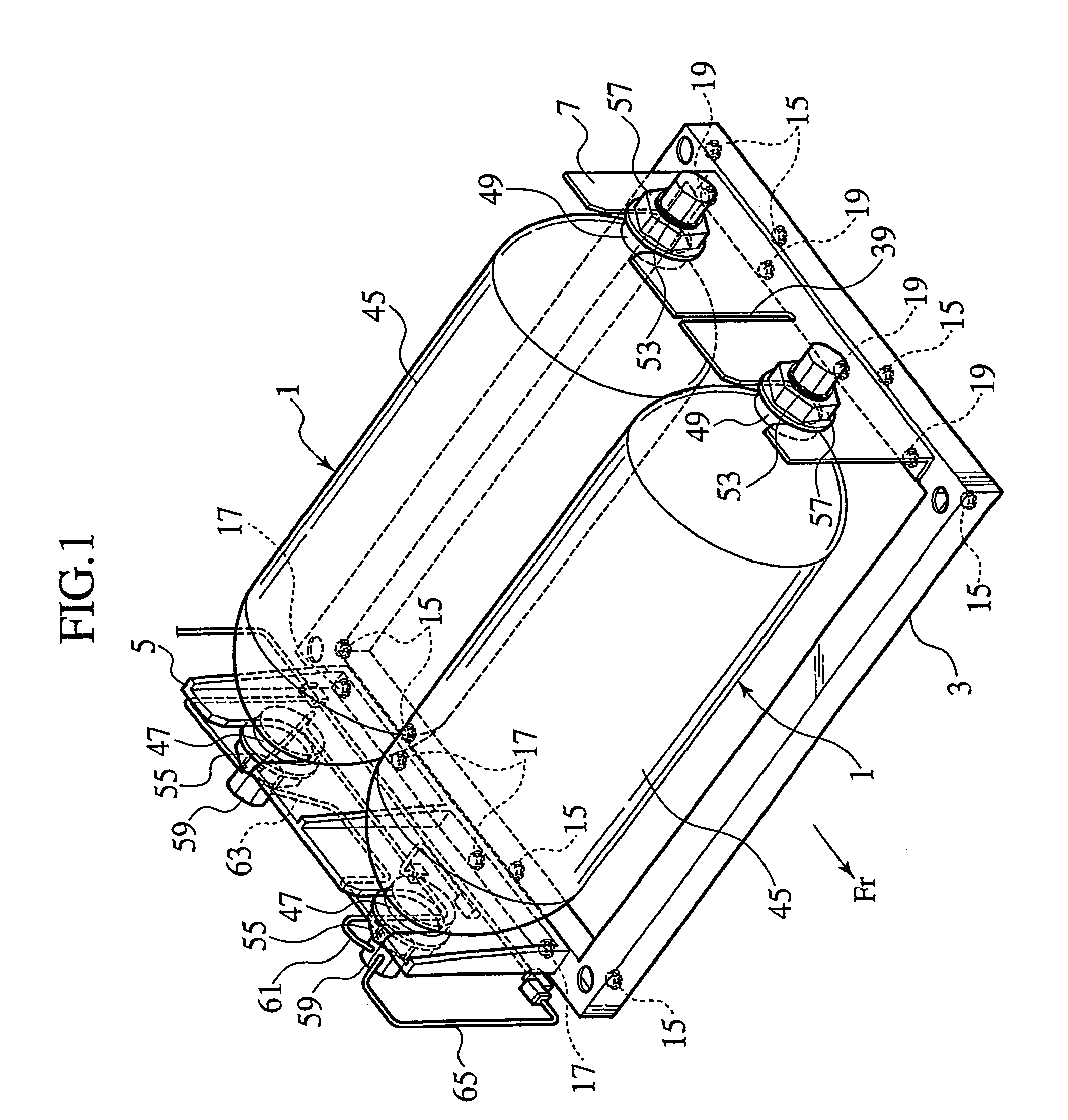
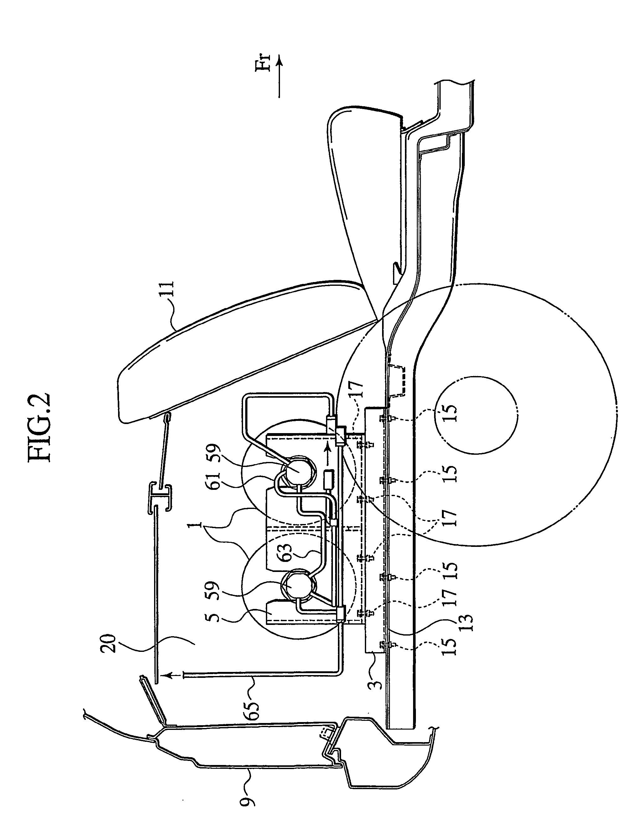
[0014]Embodiments of the present invention will be explained below with reference to the drawings, wherein like members are designated by like reference characters. Note that an arrow Fr in each of FIGS. 1 to 3 indicates a front of a vehicle body.

[0015]As shown in FIG. 1, two high pressure containers 1 are arranged in parallel with each other, supported by a pair of support members 5 and 7 provided on a square frame 3, and then stored in a trunk room 20 behind a rear seat 11 in an automotive vehicle body 9 as shown in FIG. 2. As shown in FIGS. 2 and 3, the frame 3 is fixed on a floor panel 13 in the trunk room 20 by bolts and nuts 15. The support members 5 and 7 are fixed on the frame 3 by bolts and nuts 17 and 19, respectively.

[0016]As shown in FIG. 4, the first support member 5 includes a flange 21 as a base portion to be fixed on the frame 3 by the bolts and nuts 17, a supporting plate 23 standing upright on an outer side of the flange 21 in a vehicle transverse direction (X dire...


PUM


Abstract

A support structure for a container (1) provided with neck portions (47, 49) on both ends of a longitudinal direction thereof which includes; a first support member (5) for supporting one of the neck portions (47, 49) of the container (1); a second support member (7) for supporting the other of the neck portions (47, 49) of the container (1), and elastically pressing the container (1) in the longitudinal direction thereof; and a frame (3) to which the first and second support members (5, 7) are fixed.

Description

TECHNICAL FIELD[0001]The present invention relates to a support structure of a container, particularly to a support structure of a high pressure container with neck portions at both ends of a longitudinal direction thereof.BACKGROUND ART[0002]Japanese Patent Application Laid-Open No. 2001-113962 discloses a support structure for accommodating a fuel cylinder in a concave portion on an automotive floor panel, where a main body of the cylinder is fixed by banding.DISCLOSURE OF INVENTION[0003]As the amount of fuel in the cylinder changes, an inner pressure thereof changes to expand or contract the cylinder. Particularly, an outer diameter of the main body changes to loosen the banding, resulting in failure of securing the cylinder.[0004]An object of the present invention is to provide a support structure for securing a high pressure container.[0005]An aspect of the present invention is a support structure of a container provided with neck portions on both ends of a longitudinal directi...

Claims


Application Information

Patent Timeline
IPC IPC(8): B60K15/067B60K1/04B60K15/03F02M21/02F17C13/08
CPCF17C13/084F17C2270/0168F17C2205/0192F17C2201/0109F17C2201/035F17C2201/056F17C2205/013F17C2205/0142F17C2221/012F17C2223/0123F17C2223/036F17C2270/0178F17C2270/0184Y02E60/321Y02E60/32F17C13/08
Inventor YOKOTE, MASATSUGU
Owner NISSAN MOTOR CO LTD
Why Eureka
Try Eureka