Modular connector family for board mounting and cable applications

a technology of connector family and connector plate, applied in the field of modular connector family, can solve the problem of adding to the overall cost of production

Active Publication Date: 2006-11-21
TYCO ELECTRONICS LOGISTICS AG (CH)
View PDF11 Cites 96 Cited by
  • Summary
  • Abstract
  • Description
  • Claims
  • Application Information

AI Technical Summary

Benefits of technology

[0005]In accordance with an embodiment, a connector family is provided that comprises a central housing having a connector mating face and a board mounting interface. An outer shell is shaped to fit over the central housing. The outer shell at least partially encloses the board mounting interface and exposes the connector mating interface of the central housing. The outer shell has a cable interface that is configured to be joined to a cable. Contacts are held in the central housing. The contacts, central housing and outer shell are used in different configurations depending upon the application. In a first application, the outer shell is mounted over the central housing to form a first configuration. In a second application, the outer shell is removed to expose the board mounting interface on the central housing to form a second configuration.
[0006]Optionally, the connector family may include first and second sets of contacts associated with the first and second configurations, respectively, where the second set of contacts is loaded in the central housing to be board mounted. The second set of contacts are replaced with the first set of contacts when the outer shell is provided over the central housing to form a cable assembly. Optionally, the first set of contacts may include wire crimps configured to securely grip cables and the contacts in the second set of contacts may include contact tails configured to be secured to a circuit board. The first set of contacts may be provided in the central housing for use only in the first application and not in the second application, while the second set of contacts may be provided in the central housing for use only in the second application and not in the first application.

Problems solved by technology

Separate tooling for each type of connector adds to the overall cost associated with production.

Method used


Image

  • Modular connector family for board mounting and cable applications
  • Modular connector family for board mounting and cable applications
  • Modular connector family for board mounting and cable applications

Examples


Embodiment Construction

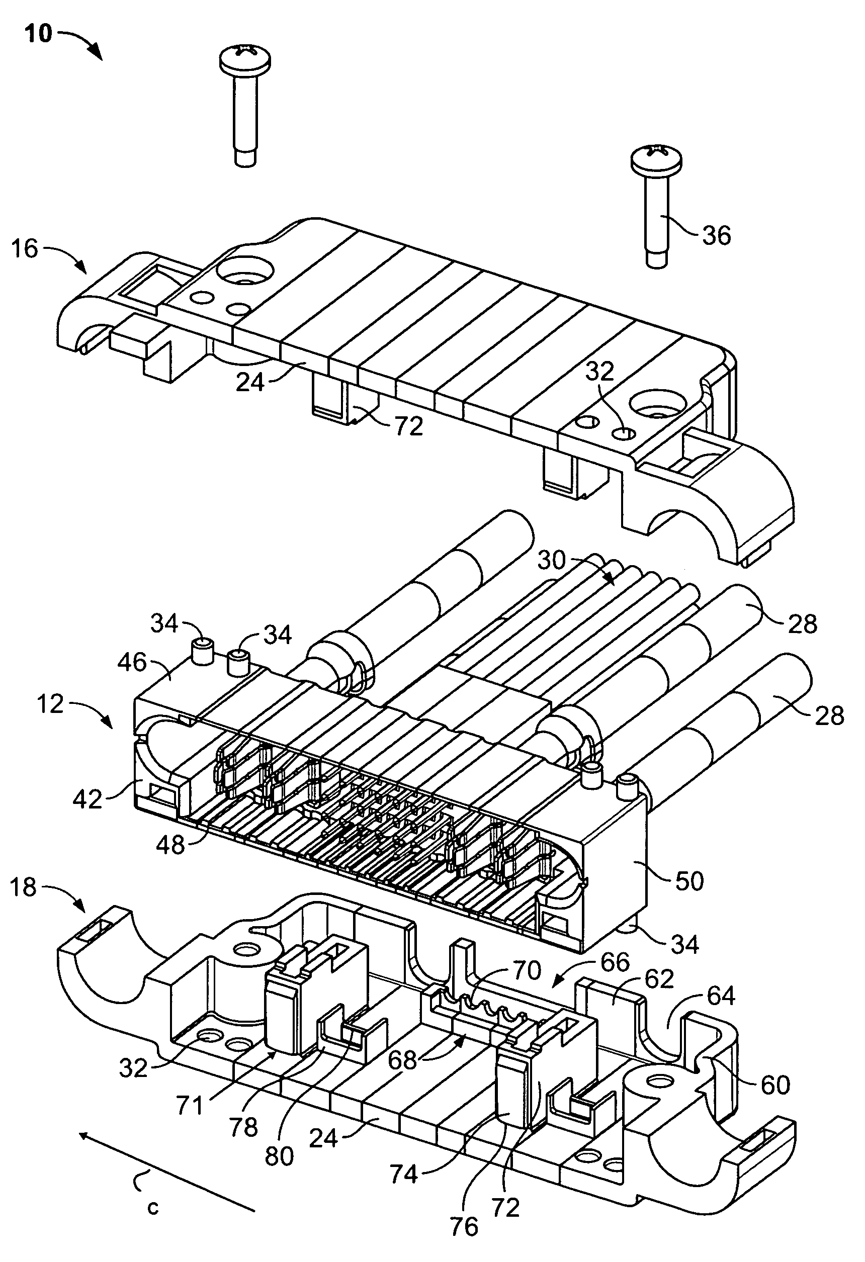
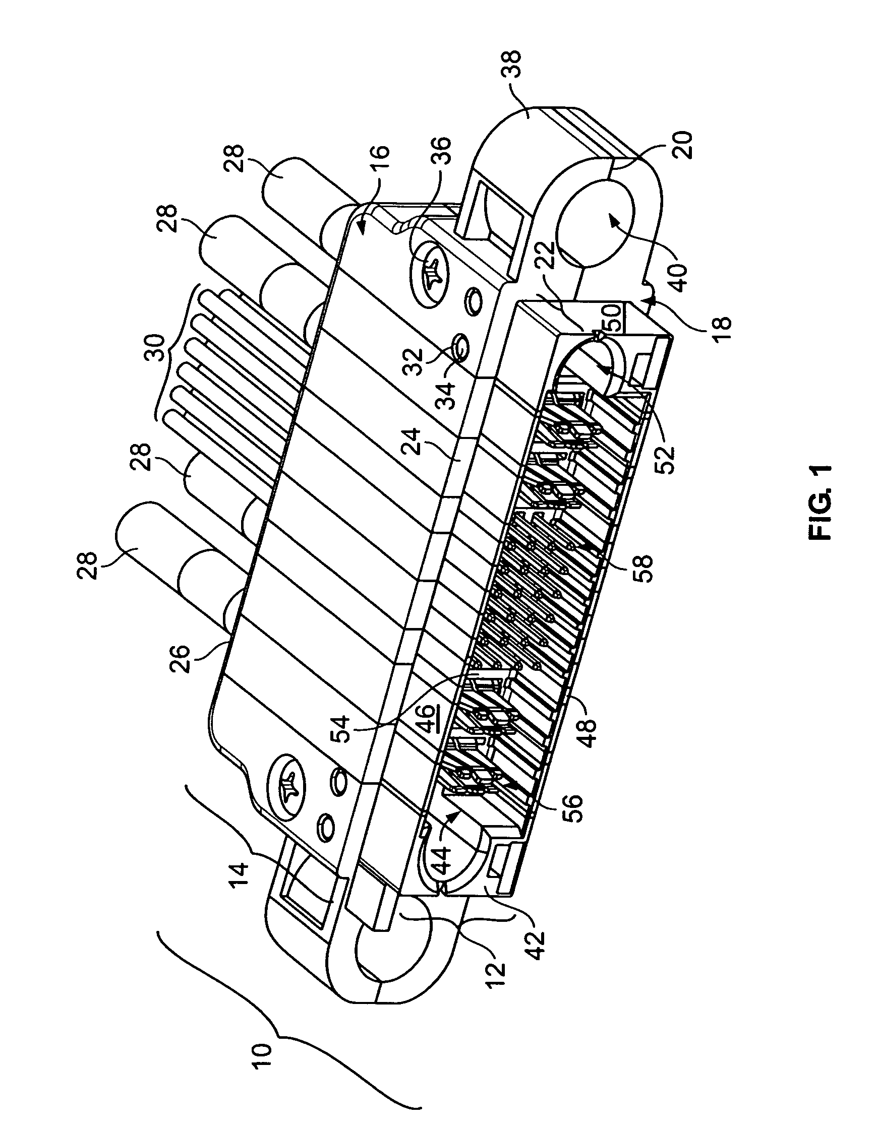
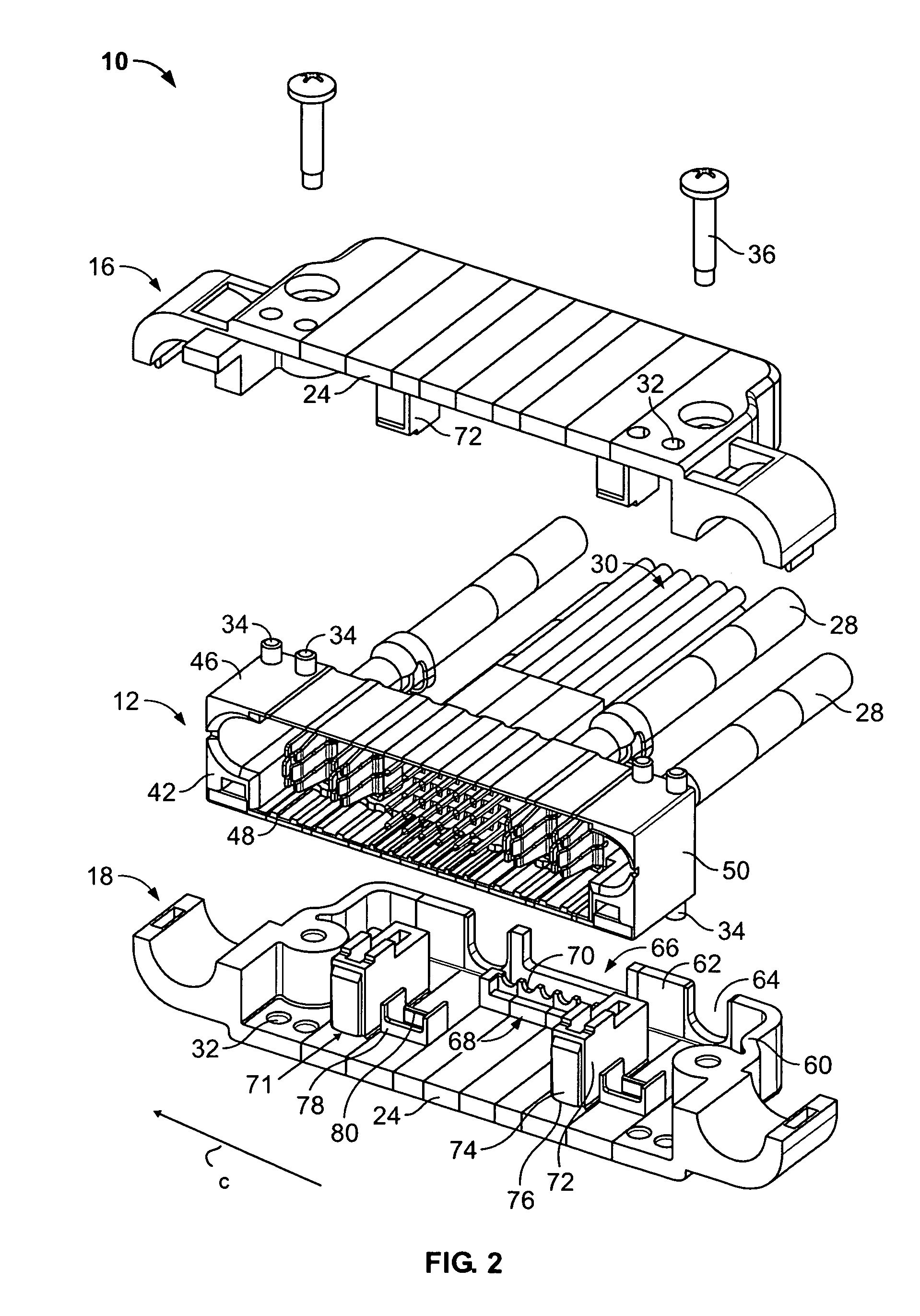
[0018]Embodiments of the present invention generally relate to connector families having multiple separable components. The components are joined in different combinations and contact patterns depending upon the intended application. A single connector family may support two or more applications. In certain embodiments described hereafter, exemplary applications include board mounting and cable assemblies, but other applications may apply. In certain embodiments, the connector family includes a common central housing (FIGS. 1, 2, 5, 6, 9 and 10) having a removable outer shell (FIGS. 1 and 2), and different sets of signal and power contacts (FIGS. 1–10). It is understood, that the components in FIGS. 1–10 form various combinations of connector families and need not all be available to form a single connector family.

[0019]FIG. 1 illustrates a cable assembly 10 formed from one connector family in accordance with an embodiment of the present invention and assembled for a cable applicati...


PUM


Abstract

A connector family that has a central housing having a connector mating face and a board mounting interface. An outer shell is shaped to fit over the central housing. The outer shell at least partially encloses the board mounting interface and exposes the connector mating interface of the central housing. The outer shell has a cable interface that is configured to be joined to a cable. Contacts are held in the central housing. The contacts, central housing and outer shell are used in different configurations depending upon the application. In a first application, the outer shell is mounted over the central housing to form a first configuration. In a second application, the outer shell is removed to expose the board mounting interface on the central housing to form a second configuration.

Description

BACKGROUND OF THE INVENTION[0001]The present invention generally relates to a modular connector family, and more specifically to a connector family having common components that may be used in both board mounting and cable applications.[0002]A wide variety of connectors exist today for various applications. For example, connectors are used to join circuit boards, to join cables, to join cables and circuit boards and the like. In general, each type of connector is designed for a specific application, and the overall construction of a connector is both tailored and streamlined for use in a given application. Most applications have different physical design and performance requirements. Thus, a connector designed for a board mounting application is optimized for the constraints and performance requirements of the board mounting application. Separately, a connector intended for a cable application is optimized to satisfy the physical and performance requirements of the cable application...

Claims


Application Information

Patent Timeline
Patent Type & Authority Patents(United States)
IPC IPC(8): H01R13/58
CPCH01R13/514H01R43/18H01R13/516H01R12/716Y10S439/947
Inventor TROUT, DAVID ALLISONWHYNE, RICHARD NICHOLASBLANCHFIELD, MICHAEL ALLEN
Owner TYCO ELECTRONICS LOGISTICS AG (CH)
Why Eureka
Try Eureka