Method of fabricating an integrated circuit channel region

a technology of integrated circuits and channel regions, applied in the field of integrated circuits, can solve the problems of difficult manufacturing of double gate structures using conventional ic fabrication tools and techniques, complicated and expensive equipment, and inability to mass produce ics

Active Publication Date: 2006-11-21
GLOBALFOUNDRIES U S INC
View PDF12 Cites 70 Cited by
  • Summary
  • Abstract
  • Description
  • Claims
  • Application Information

AI Technical Summary

Problems solved by technology

However, the MBE technique requires very complicated and expensive equipment, and is not feasible for mass production of ICs.
However, double gate structures can be difficult to manufacture using conventional IC fabrication tools and techniques.
Further, patterning can be difficult because of the topography associated with a silicon fin.
At small critical dimensions, patterning may be impossible.
Various problems can exist with such a configuration.
Such a configuration leads to large over-etch requirements for the BARC layer and the polysilicon layer.
Such requirements increase the size of the transistor.
Heretofore, fabrication of high aspect ratio FinFETS has not been practicable for large-scale fabrication.

Method used


Image

  • Method of fabricating an integrated circuit channel region
  • Method of fabricating an integrated circuit channel region
  • Method of fabricating an integrated circuit channel region

Examples


Embodiment Construction

[0032]FIG. 1 is a flow diagram depicting exemplary operations in a method or process 10 of patterning a fin-based transistor or fin field effect transistor (FinFET). The flow diagram illustrates by way of example some operations that may be performed. Additional operations, fewer operations, or combinations of operations may be utilized in various different embodiments. Flow diagram 110 (FIG. 12) illustrates on alternative embodiment in which a masking step is used to protect source and drain locations during etching. Flow diagram (FIG. 15) illustrates another alternative embodiment in which a spacer is utilized to increase the aspect ratio of the fin structure.

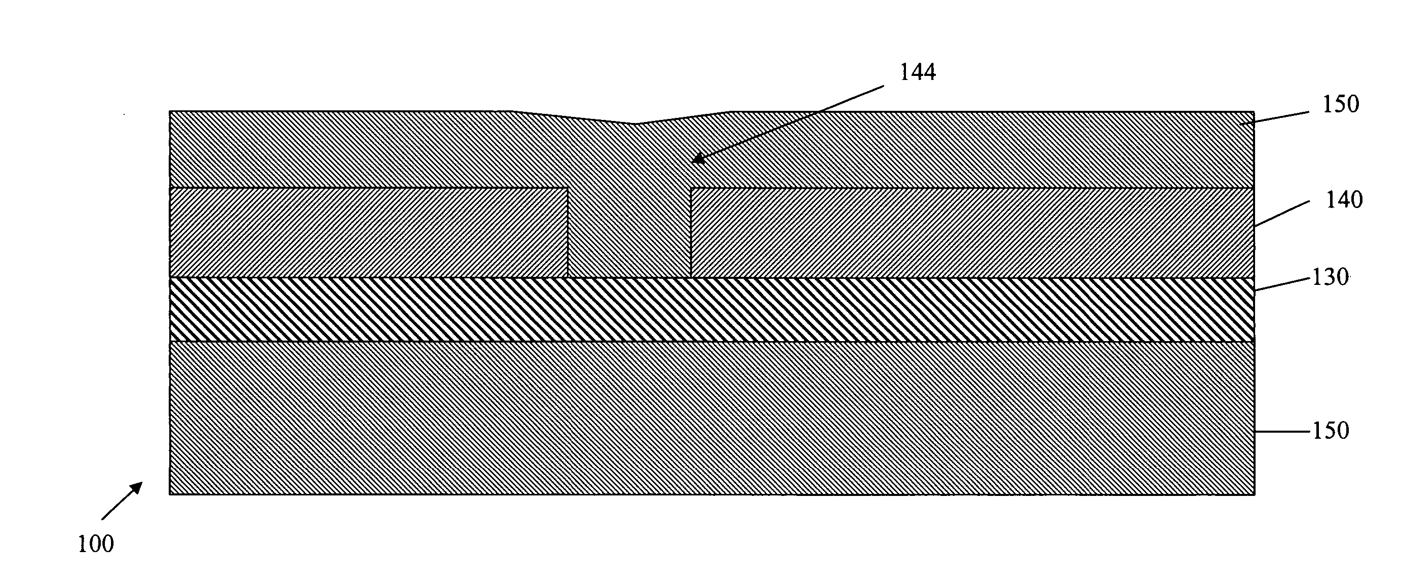
[0033]In FIG. 1, a wafer including a compound semiconductor layer over an insulative layer is provided in a step 15. The wafer can be purchased or manufactured using SIMOX (oxygen implementation into silicon and annealing or wafer bonding). In a step 25, the compound semiconductor layer is patterned to form a channel trench. ...


PUM


Abstract

An exemplary embodiment relates to a method of FinFET channel structure formation. The method can include providing a compound semiconductor layer above an insulating layer, providing a trench in the compound semiconductor layer, and providing a strained semiconductor layer above the compound semiconductor layer and within the trench. The method can also include removing the strained semiconductor layer from above the compound semiconductor layer, thereby leaving the strained semiconductor layer within the trench and removing the compound semiconductor layer to leave the strained semiconductor layer and form the fin-shaped channel region.

Description

CROSS REFERENCE TO RELATED APPLICATIONS[0001]The present application is related to U.S. patent application No. 10 / 755,811 filed on Jan. 12, 2004 by Goo et al. and entitled “REPLACEMENT GATE FINFET PROCESS”; U.S. patent application Ser. No. 10 / 237,829, filed on Sep. 9, 2002 by Tabery et al. and entitled “PLANAR FINFET PATTERNING USING AMORPHOUS CARBON”; and U.S. Patent Application No. 60 / 415,226, filed on Sep. 30, 2002 by Goo et al. and entitled “FINFET HAVING IMPROVED CARRIER MOBILITY AND METHOD OF ITS FORMATION”, all of which are assigned to the Assignee of the present application.FIELD OF THE INVENTION[0002]The present invention relates generally to integrated circuits (ICs) and methods of manufacturing integrated circuits. More particularly, the present invention relates to a method of fabricating integrated circuits having transistors with a fin-shaped channel region or FinFETS.BACKGROUND OF THE INVENTION[0003]Integrated circuits (ICs), such as ultra-large-scale integrated (ULSI...

Claims


Application Information

Patent Timeline
Patent Type & Authority Patents(United States)
IPC IPC(8): H01L21/335H01L21/338H01L21/8249H01L21/84H01L27/01H01L21/336H01L29/786
CPCH01L29/66795H01L29/785H01L29/7842H01L21/18
Inventor XIANG, QIPAN, JAMES N.GOO, JUNG-SUK
Owner GLOBALFOUNDRIES U S INC
Why Eureka
Try Eureka