Adjustable rifle scope mount

a scope mount and adjustable technology, applied in the direction of weapons, sighting devices, weapon components, etc., can solve the problems of not being able to easily reach the internal adjustment mechanism, the adjustment markings cannot be readily read, and the internal adjustment mechanism of most telescopic scopes is less accurate over the outer portion of the adjustment range, so as to achieve smooth and accurate transmission, make elevation adjustments quickly, and quiet

Inactive Publication Date: 2006-11-28
IVEY STEPHEN
View PDF20 Cites 52 Cited by
  • Summary
  • Abstract
  • Description
  • Claims
  • Application Information

AI Technical Summary

Benefits of technology

[0019]Accordingly it is an object of the present invention to provide an adjustable mounting system for a telescopic scope having an elevation adjustment dial adapted to provide smooth and accurate transmission for bi-directional travel of the elevation cam.
[0020]It is an additional object of the pres...

Problems solved by technology

These internal adjustment mechanisms of most telescopic scopes are less accurate over the outer portion of their adjustment ranges.
The internal adjustment mechanisms frequently are positioned such that a shooter in the firing position cannot easily reach the internal adjustment mechanisms and cannot readily read the adjustment markings.
Additionally, the internal adjustment mechanisms of telescopic scopes may be inadvertently displaced by acceleration experienced during recoil and other shocks.
When hunting in rough terrain, obstacles may strike these exposed elevation adjusting dials and cause movement and misadjustment of the elevation adjustment set in the mounti...

Method used


Image

  • Adjustable rifle scope mount
  • Adjustable rifle scope mount
  • Adjustable rifle scope mount

Examples


Embodiment Construction

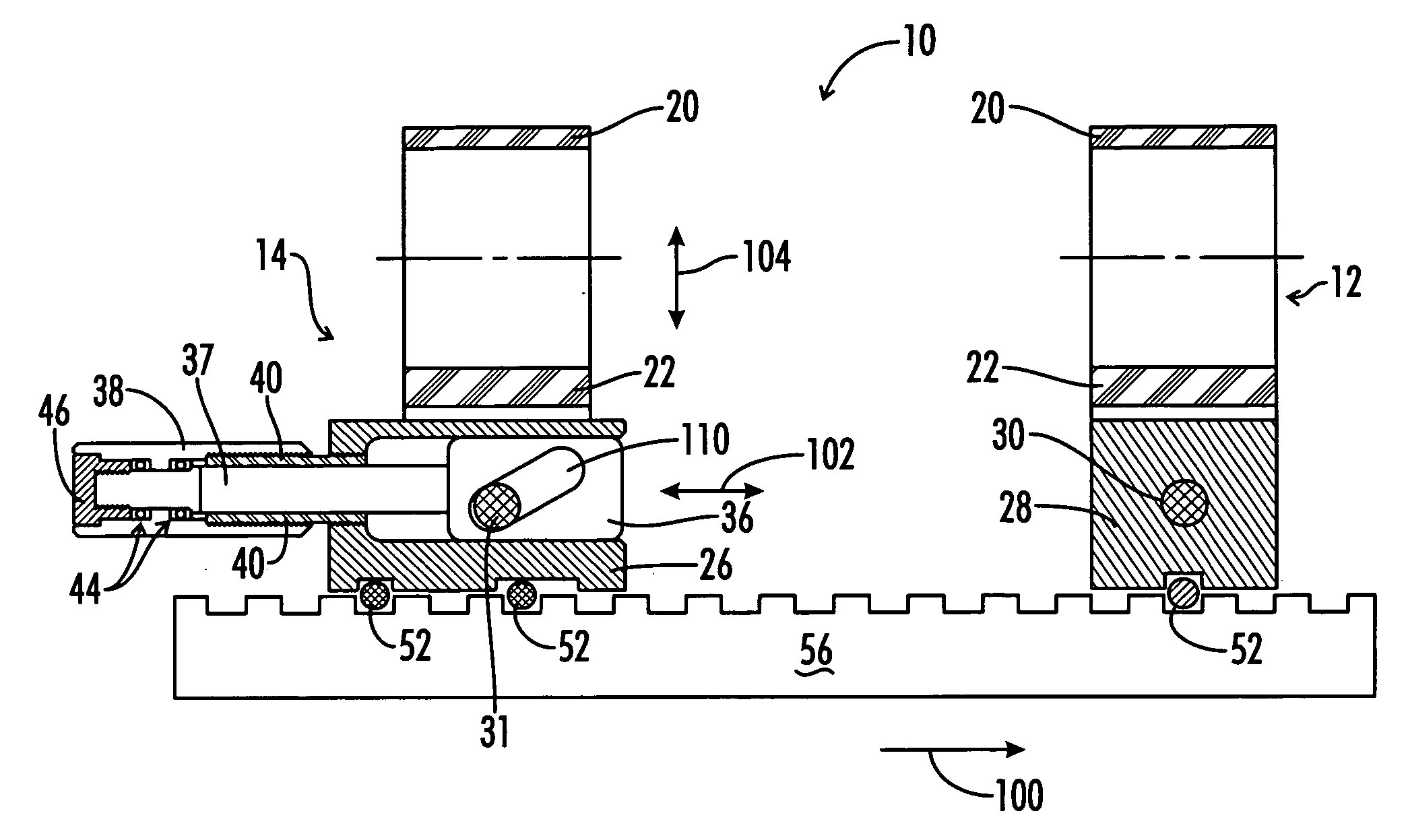
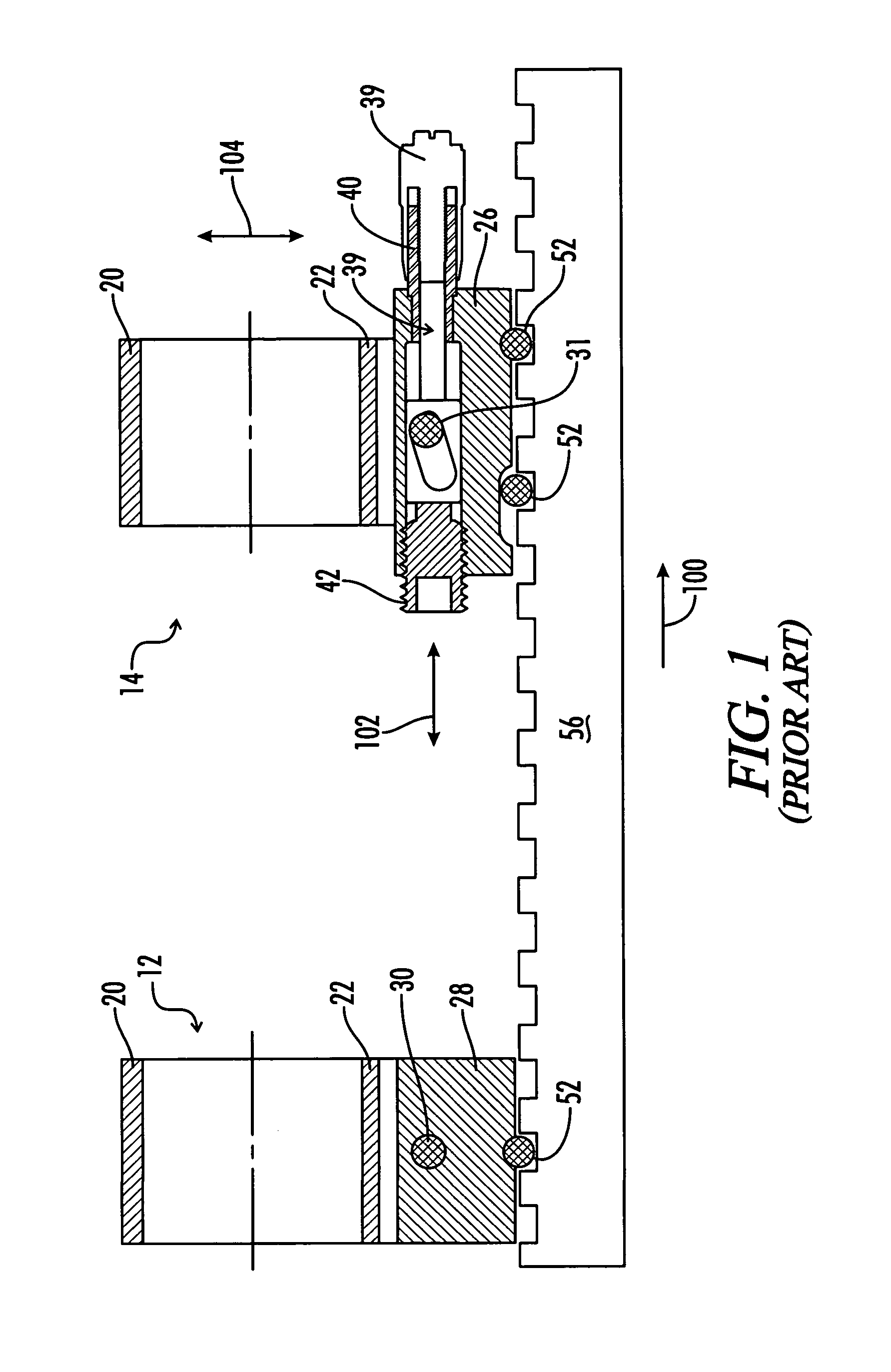
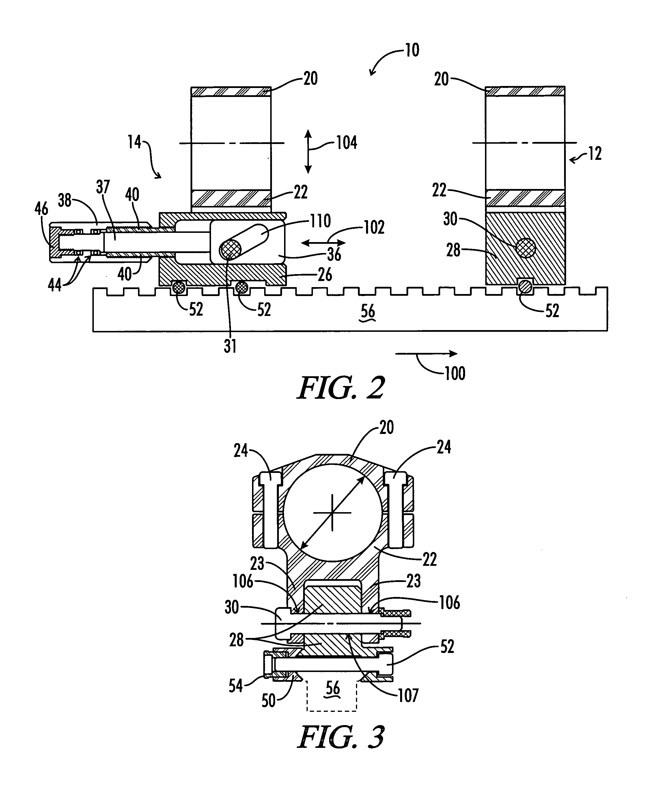
[0028]One preferred embodiment of the present invention is shown in FIGS. 2, 3 and 4. This embodiment of the mounting system 10 of the present invention is adjustable within 1.0 m.o.a. graduations between 0 m.o.a. and 150.0 m.o.a. This embodiment incorporates the scope rings and pivoting mount 12 of the Ivey 50 MOA mounting system, with the exception that a ratchet lever 32 is used to tighten or loosen the pivot pin 30. This modification allows for rapid, quiet tightening or loosening the pivot pin 30 without the use of external tools.

[0029]Referring to FIG. 2, the mounting system of the present invention includes a pivoting mount 12 located forward of the adjustable elevation mount 14 as indicated by the direction arrow 100. The elevation adjustment dial 38 is disposed in the rear portion of the adjustable elevation mount 14 and extends longitudinally further rearward. When in a shooting position, this configuration places the elevation adjustment dial adjacent to the shooter's eye...


PUM


Abstract

An adjustable mounting system for a telescopic scope includes an adjustable elevation mount formed from a scope ring and an adjustable sub-base. A clevis portion of the scope ring holds an elevation pin that is received by a vertical slot in the adjustable sub-base. An internally longitudinal bore is disposed though the adjustable sub-base and an externally threaded barrel disposed in an opening of the longitudinal bore. A cylindrical elevation cam having an angled slot is disposed in the longitudinal bore and includes a positioning rod that extends through a bore disposed through the barrel. The angled slot receives the elevation pin as it extends through the vertical slot of the adjustable sub-base. The positioning rod has a shoulder portion that receives a set of roller thrust bearings and has a threaded distal end. An internally threaded dial thimble extends over the positioning rod distal end and shoulder portion to engage the external threads of the barrel. A thimble locking nut engages the threaded distal end of the positioning rod so as to affix the dial thimble to the positioning rod. Bi-directional longitudinal travel of the elevation cam is accomplished by rotation of the dial thimble.

Description

BACKGROUND OF THE INVENTION[0001]The present invention relates generally to an apparatus and method of attaching and aligning an optical targeting or alignment system to a base. More particularly, this invention pertains to an apparatus and method of attaching and aligning optical sighting systems to a ballistic launcher. Even more particularly, this invention pertains to an adjustable mounting system for a telescopic scope.[0002]It is long known in the art to provide mechanical means for adjusting the elevation of sighting and ranging devices mounted to a base. Aiming or sighting devices, laser target illumination devices and laser ranging devices are commonly mounted to ballistic projectile launchers, such as rifles, to survey equipment, and to other apparatus requiring alignment along a longitudinal axis. Common aiming or sighting devices include various types of telescopic optical scopes. Other aiming or sighting devices include telescopic and non-telescopic thermal imaging scop...

Claims


Application Information

Patent Timeline
IPC IPC(8): F41G1/387
CPCF41G11/003
Inventor IVEY, STEPHEN
Owner IVEY STEPHEN
Why Eureka
Try Eureka