Portable luggage carts/carriers

a luggage cart and carrier technology, applied in the field of luggage carts, can solve the problems of inability to fully satisfy all consumers' needs and demands, inability to provide repeatable, reliable, controlled movement of the support wheels, etc., and achieve the effects of convenient movement, convenient and quick arcuation, and convenient movemen

Active Publication Date: 2006-11-28
CONAIR CORP
View PDF30 Cites 31 Cited by
  • Summary
  • Abstract
  • Description
  • Claims
  • Application Information

AI Technical Summary

Benefits of technology

[0013]By employing the present invention, all of the difficulties and drawbacks found in the prior art constructions have been eliminated and a small, compact, two wheeled, luggage cart / carrier is achieved which is capable of quickly and easily arcuately pivoting wheel support brackets between two alternate positions, with ease and convenience. In accordance with the present invention, the arcuate pivoting movement of the wheel supporting brackets is automatically achieved simultaneously with movement of the luggage support platform from a stowed position to a deployed, usable position.
[0014]In accordance with the present invention, the luggage cart / carrier is constructed with a frame assembly, two wheel holding carriers which are arcuately pivotably mounted to the frame assembly, and a support platform which is also pivotally mounted to the frame assembly. In the preferred construction, the pivotal movement of the support platform relative to the frame assembly automatically controls the arcuate pivoting movement of the two wheel holding carriers. Furthermore, for added convenience, the frame member is constructed for being folded into a small, compact area.
[0015]In the present invention, the support platform is pivotally mounted to the terminating end of the frame assembly for being arcuately pivoted between a first, stowed position and a second, deployed position wherein the support platform is substantially perpendicular to the plane established by the frame assembly. In addition, in the preferred construction, the support platform is affixed to a pair of brackets, each of which are pivotally mounted to the opposed ends of the frame assembly and cooperate with the wheel holding carriers to cause the wheel holding carriers to arcuately pivot. In this way, the movement of the support platform from its stowed position into its deployed position simultaneously causes the wheel holding carriers to pivot about 90° from the stowed position to the useable position wherein the wheels support any items placed on the platform and enable the items and the entire cart / carrier to be easily moved.
[0016]In the preferred construction, each wheel holding carrier is pivotally mounted to the frame assembly, with the arcuate movement thereof controlled by a torsion spring or coil spring associated therewith. By mounting the spring members to the frame assembly and to a collar mounted to the frame assembly, the movement of the support platform causes the frame legs to axially move relative to the wheel holding carriers while simultaneously changing the effective length of the spring members. As a result, arcuate pivoting movement of the wheel holding carriers is achieved.

Problems solved by technology

Although this type of construction quickly became popular, difficulties were often encountered with prior art constructions due to their inability to provide repeatable, reliable, controlled movement of the support wheels in a cost effective construction.
However, although substantial effort has been expended in attempting to develop a reliable and dependable construction, these efforts have generally failed to fully satisfy all of the consumers needs and demands.
In particular, these prior art products are typically constructed with extremely complicated pivoting systems, requiring numerous parts and assembly difficulties.
As a result, substantial expense is incurred in the manufacture of these products, as well as suffering from breakdowns and operational malfunctions.
In addition, other prior art products are constructed with activation systems which are susceptible to jamming or failure during the opening operation.
In addition, some systems require sliding engagement of metal parts which are prone to incur jamming during repeated use.
As a result, these prior art systems are frequently difficult to operate and have proven to be unacceptable to consumers, due to these difficulties.

Method used


Image

  • Portable luggage carts/carriers
  • Portable luggage carts/carriers
  • Portable luggage carts/carriers

Examples


Embodiment Construction

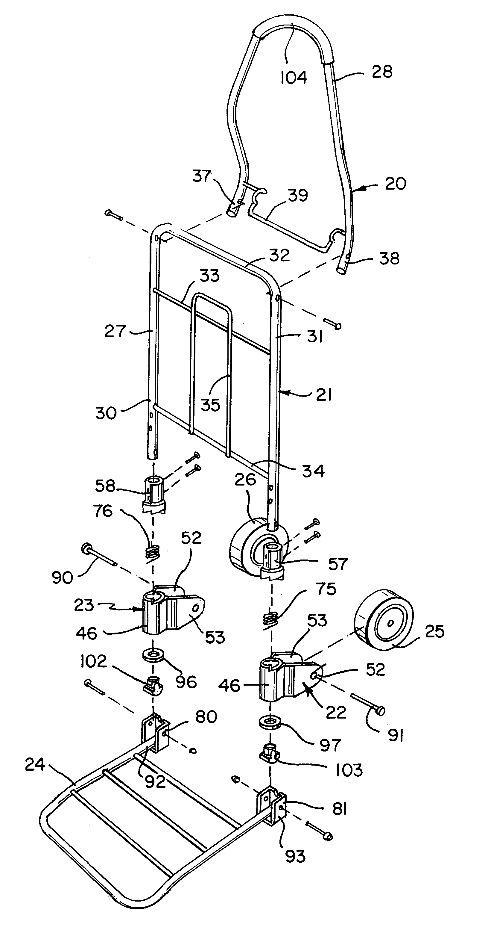
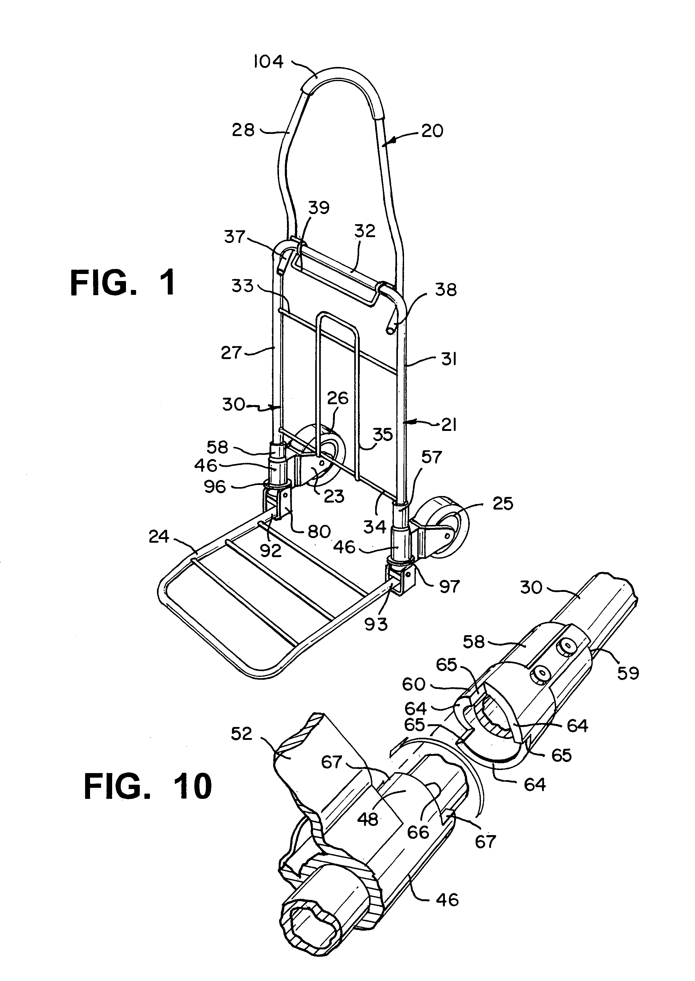
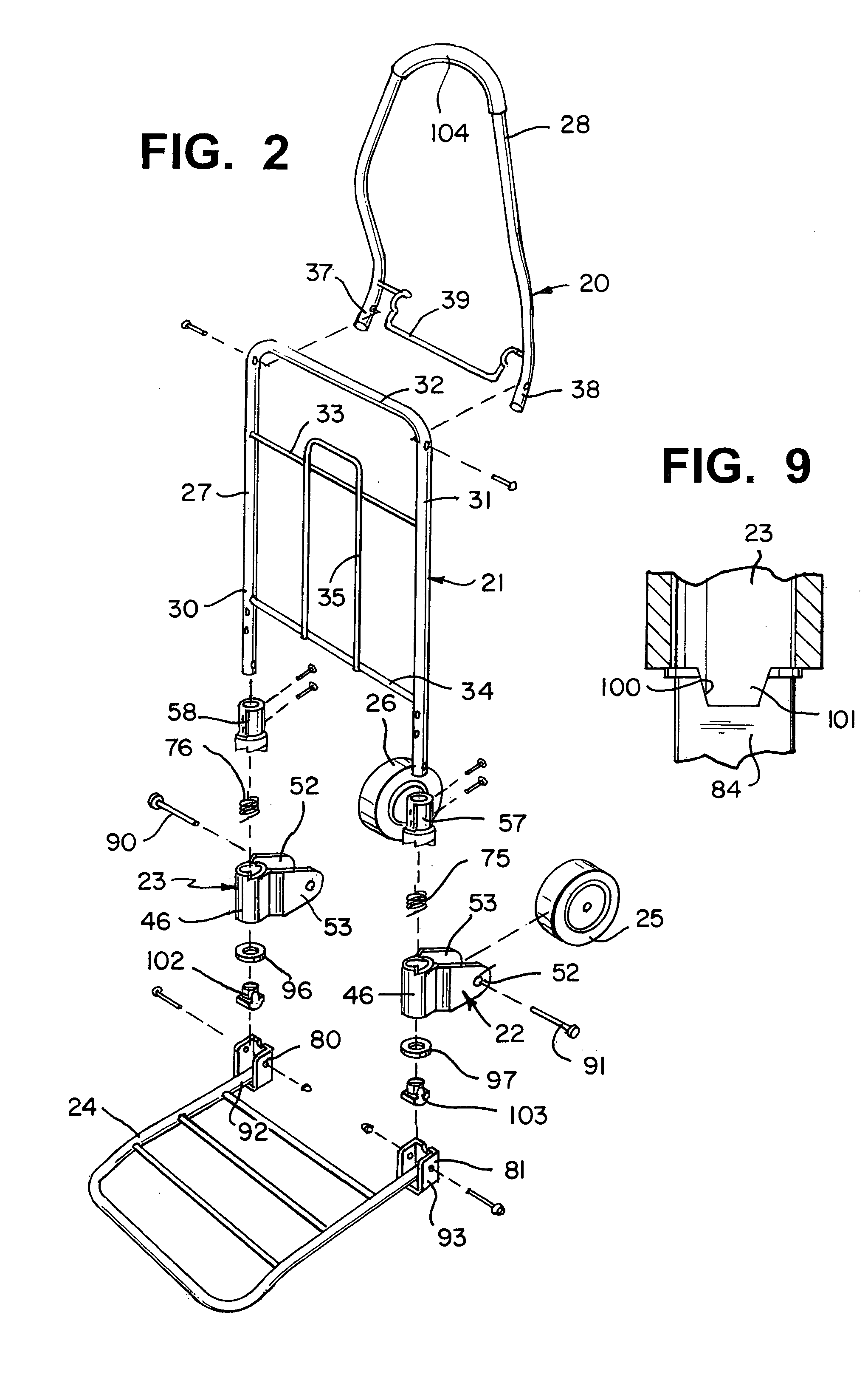
[0031]By referring to FIGS. 1–9, along with the following detailed discussion, the construction and operation of the preferred embodiment of luggage cart / carrier 20 of the present invention can best be understood. Although this disclosure provides the best mode known to the Applicant for the present invention, alternate constructions and variations can be implemented without deviating from the scope of the present invention. Consequently, it is to be recognized that this disclosure is provided for exemplary purposes only and is not intended as a limitation of the present invention.

[0032]As the best seen in the FIGS. 1–5, luggage cart / carrier 20 principally incorporates frame assembly 21, wheel holding carriers 22 and 23, support platform 24, and wheels 25 and 26. In the preferred construction, frame assembly 21 comprises a generally U-shaped, principally tubular frame member 27 and curved, handle extension 28. As depicted, and as further detailed below, handle extension 28 is prefer...


PUM


Abstract

By providing a frame assembly, two wheel holding carriers which are arcuately pivotably mounted to the frame assembly, and a support platform which is also pivotally mounted to the frame assembly and controls the movement of the wheel holding carrier, a small, compact, two wheeled, luggage cart/carrier is achieved which is capable of quickly and easily arcuately pivoting wheel support brackets between two alternate positions, with ease and convenience. In addition, the arcuate pivoting movement of the wheel supporting brackets is automatically achieved simultaneously with movement of the luggage support platform from a stowed position to a deployed, usable position. The support platform is pivotally mounted to the terminating end of the frame assembly for being arcuately pivoted between a first, stowed position and a second, deployed position wherein the support platform is substantially perpendicular to the plane established by the frame assembly.

Description

TECHNICAL FIELD[0001]This invention relates to luggage carts and, more particularly, to two-wheeled portable luggage carts or carriers which are completely foldable and portable.BACKGROUND ART[0002]In order to accommodate the diverse needs and desires of consumers, numerous luggage cart constructions have been developed over the years. In this regard, many prior art constructions presently exist which enable consumers to easily transport a plurality of suitcases on a single cart or carrier which is also easily folded or collapsed into a small, compact configuration.[0003]As these prior art, portable, luggage carts / carriers were developed, numerous alternate designs were implemented for increasing consumer convenience. In this regard, one area which received particular attention was the construction of a luggage cart / carrier wherein the support wheels automatically arcuately pivot between a stowed position and a fully deployed, usable position. Although this type of construction quic...

Claims


Application Information

Patent Timeline
Patent Type & Authority Patents(United States)
IPC IPC(8): B62B1/12B62B1/00
CPCB62B1/12B62B2205/12
Inventor JOHNSON, CHRISMCMILLAN, A. C.
Owner CONAIR CORP
Why Eureka
Try Eureka