Distributed pipeline scheduling method and system

a pipeline scheduling and distribution pipeline technology, applied in data switching networks, time-division multiplexing selection, multiplex communication, etc., can solve the problem of difficult to flexibly cope with an increase in severe limitations are imposed on the number of ports, and the number of terminals of the lsi becomes too large to integrate the ims into one lsi

Inactive Publication Date: 2006-11-28
NEC CORP
View PDF5 Cites 14 Cited by
  • Summary
  • Abstract
  • Description
  • Claims
  • Application Information

AI Technical Summary

Benefits of technology

[0030]It is an object of the present invention to provide a distributed pipeline scheduling method and system which are tolerant of processing time limitations.

Problems solved by technology

This makes it difficult to flexibly cope with an increase in the number of ports by using the conventional algorithm.
Since the total time of these times and the above reservation processing time must be limited within one time slot, severe limitations are imposed on the number of ports.
When, therefore, IMs are to be implemented by a Large Scale Integration (LSI), the number of terminals of the LSI becomes too large to integrate the IMs into one LSI.

Method used


Image

  • Distributed pipeline scheduling method and system
  • Distributed pipeline scheduling method and system
  • Distributed pipeline scheduling method and system

Examples


first embodiment

[0064]FIG. 4 shows scheduling operation of the present invention. This operation is scheduling operation based on framed RRGS. FIG. 4 shows case where module count N=4, and a method of determining a reservation sequence from TS9. The encircled time slot numbers (TS9 to TS20) indicate time slots that are reserved by a series of pipeline operations.

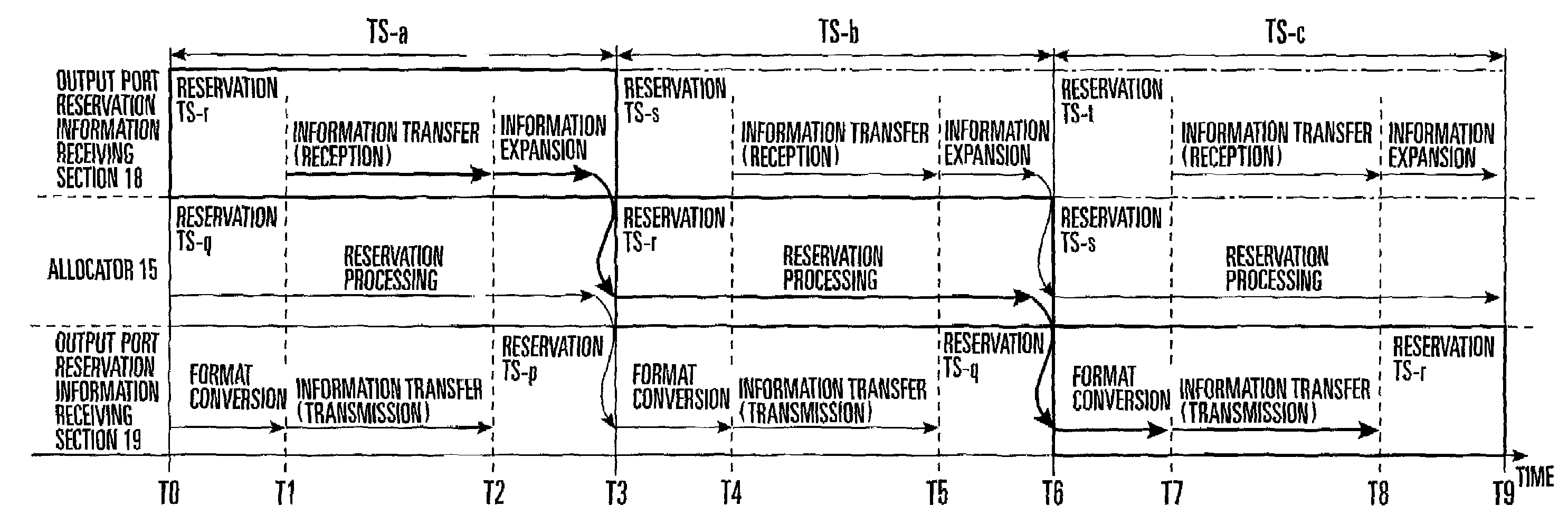
[0065]Time slots in which IM numbers (IM1 to IM4) are written indicate time slots in which reservation processing is executed. Time slots in which arrows are written indicate time slots in which format conversion processing, transfer processing, and expansion processing of reservation output port information are executed. The last curved arrow indicates a time slot as a reservation target.

[0066]Consider the correspondence between the operations in FIGS. 3 and 4. Referring to FIG. 4, for example, IM2 executes reservation processing for TS9 in the interval between TS2 and TS4. This corresponds to reservation processing for TS-r in the interva...

second embodiment

[0072]FIG. 5 shows scheduling operation in the present invention. This operation is also scheduling operation based on framed RRGS. FIG. 5 shows a case where module count N=4, and a method of determining a reservation sequence from TS9.

[0073]The following is the difference between this embodiment and the first embodiment of the present invention shown in FIG. 4. In the first embodiment, the combination of reservation time slots for which processing is started from TS1 are TS9, TS10, TS11, and TS12, and the combination of reservation time slots for which processing is started from TS2 are TS13, TS14, TS15, and TS16. In contrast to this, in this embodiment, reservation time slots for which processing is started from TS1 are TS9, TS11, TS13, and TS15, and reservation time slots for which processing is started from TS2 are TS10, TS12, TS14, and TS16.

[0074]As shown in FIG. 5, in the second embodiment as well, TS1 is a start reservation time slot. As in the first embodiment, connection re...

third embodiment

[0075]FIG. 6 shows scheduling operation in the present invention. This operation is scheduling operation based on RRGS. FIG. 6 shows a case where the number of modules used is an even number, i.e., N=4, and a method of determining a reservation sequence from TS9.

[0076]Scheduling for TS9 is started from a distributed scheduling module IM1 in TS1. In TS3, a distributed scheduling module IM2 performs reservation processing. In TS5, a distributed scheduling module IM3 performs reservation processing. In TS7, a distributed scheduling module IM4 performs reservation processing. In TS2, TS4, and TS6, transfer processing is performed. Subsequently, scheduling for TS10 is started from the distributed scheduling module IM4 in TS2. In TS4, the distributed scheduling module IM1 performs reservation processing. In TS6, the distributed scheduling module IM2 performs reservation processing. In TS8, the distributed scheduling module IM3 performs reservation processing. In TS3, TS5, and TS7, transfe...


PUM


Abstract

In a distributed pipeline scheduling method for a system which includes a plurality of input ports for inputting data, a plurality of output ports for outputting data, a data switch element for switching the data input from the input ports and transferring the data to the output ports, and a scheduler having a distributed scheduling architecture for controlling the data switch element, and determines connection reservations between the input ports and the output ports, the scheduler independently assigns time slots to information transfer processing and reservation processing. Processing information transfer processing and reservation processing are performed in the assigned time slots in a pipeline fashion. A distributed pipeline scheduling system and distributed scheduler are also disclosed.

Description

BACKGROUND OF THE INVENTION[0001]The present invention relates to a packet switching system and, more particularly, to a pipeline scheduling method and system for the packet switch of a packet switching system.[0002]Some recent packet switching systems use an input buffer type switch having N inputs and N outputs (N is a natural number) and N virtual output queuing (VOQ) elements in each input section.[0003]FIG. 8 shows a conventional, general input buffer type packet switch having N inputs and N outputs (N is a natural number). Referring to FIG. 8, a packet switch 40 includes a plurality of input ports for inputting data, a plurality of output ports for outputting data, a data switch element 54 for transferring data input from the input ports to the output ports by switching them, and a scheduler 50 for controlling the data switch element 54.[0004]Each input port has virtual output queuing (VOQ) elements 52. As the switch element 54, a cross-bar switch may be used. The scheduler 50...

Claims


Application Information

Patent Timeline
Patent Type & Authority Patents(United States)
IPC IPC(8): H04L12/28H04L12/56H04B7/26H04L12/70H04L12/937H04Q11/04
CPCH04B7/2643H04L49/3081H04Q11/0478H04L2012/5679
Inventor KAMIYA, SATOSHI
Owner NEC CORP
Why Eureka
Try Eureka