Device and method to locally fill gaps in spotbeam satellite systems with frequency re-use

a satellite system and spotbeam technology, applied in the field of system and method for improving the transmission capacity of satellite broadcast systems, can solve the problems of reducing the capacity delivered to a given user, reducing the total number of rf channels used for conus capacity, and further complicated problems, so as to improve the capacity available to a given subscriber region, and reduce the cost of outdoor electronics

Inactive Publication Date: 2006-11-28
THE DIRECTV GRP INC
View PDF127 Cites 43 Cited by
  • Summary
  • Abstract
  • Description
  • Claims
  • Application Information

AI Technical Summary

Benefits of technology

[0012]To address the requirements described above, the present invention discloses a system, device and method for transmitting and receiving diverse signals across regions with improved frequency re-use (i.e. a minimizing frequency use) and without affecting expensive existing infrastructure.
[0015]A typical method of the invention comprises receiving a first signal, receiving a second signal, generating a first intermediate frequency (IF) signal from the first signal, generating a second IF signal from the second signal, filtering the second IF signal to produce a filtered second IF signal and combining the filtered second IF signal and the first IF signal. Additional processing may be performed to prevent interference between signals at the same IF frequency.

Problems solved by technology

Limited available electromagnetic spectrum requires such systems to maximize the use of available spectrum.
In this case, the problem may be further complicated if maintaining compatibility with heritage devices is desirable.
However, such systems reduce the capacity delivered to a given user because the total number of RF channels used for CONUS capacity is reduced when channels are assigned to spotbeam use.

Method used


Image

  • Device and method to locally fill gaps in spotbeam satellite systems with frequency re-use
  • Device and method to locally fill gaps in spotbeam satellite systems with frequency re-use
  • Device and method to locally fill gaps in spotbeam satellite systems with frequency re-use

Examples


Embodiment Construction

[0023]In the following description, reference is made to the accompanying drawings which form a part hereof, and which is shown, by way of illustration, several embodiments of the present invention. It is understood that other embodiments may be utilized and structural changes may be made without departing from the scope of the present invention.

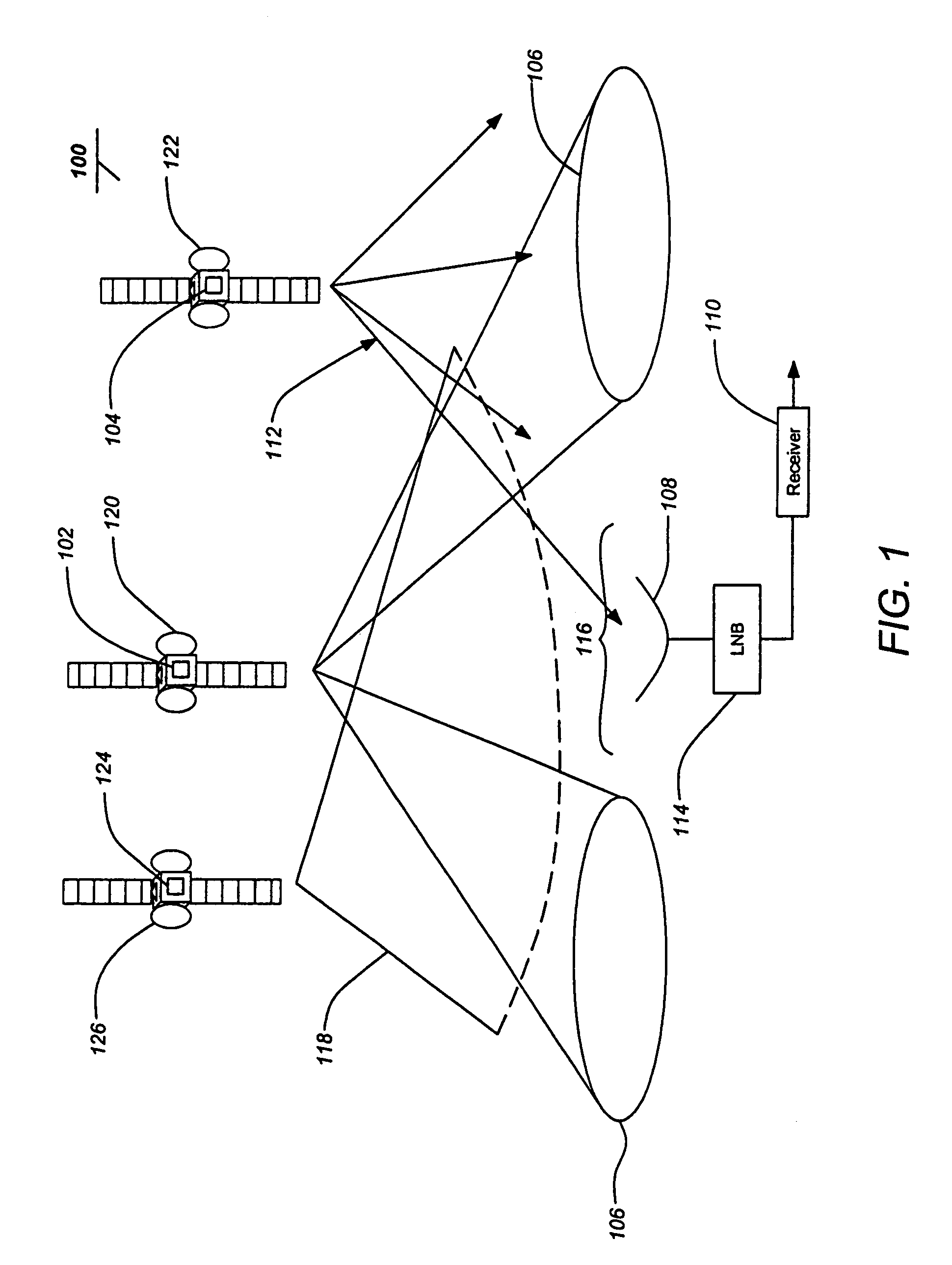
[0024]FIG. 1 is a diagram illustrating an embodiment of a transmission system 100 of the invention. At least one set of reuse transmitters 102, such as on a satellite 120 or other platform, generates a plurality of spotbeams signals 106 in a first frequency band producing a plurality of coverage regions with at least one coverage gap 116. The spotbeam signals 106 are in addition to the ordinary CONUS signal 118 transmitted from the first satellite 126 or another satellite 120 which may be in the same first frequency band. Gapfiller transmitters 104, which may be located on the first satellite 120 or platform or a separate satellite 122 or pl...


PUM


Abstract

Systems and methods for transmitting and receiving diverse signals across regions using a minimum of frequency capacity and maintaining compatibility with the heritage system. A system of the invention comprises at least one broadcast transmitter for transmitting a broadcast signal in a first frequency band to a receiver, at least one gapfiller transmitter for transmitting a gapfiller signal in a second frequency band to the receiver and at least one set of reuse transmitters for transmitting a plurality of spotbeam signals in the first frequency band to define coverage regions and at least one coverage gap where the spotbeam signals are not transmitted. A method of the invention comprises receiving a first signal, receiving a second signal, generating a first intermediate frequency (IF) signal from the first signal, generating a second IF signal from the second signal, filtering the second IF signal to produce a filtered second IF signal and combining the filtered second IF signal and the first IF signal.

Description

[0001]This application is a continuation of U.S. application Ser. No. 09 / 796,781 filed Feb. 27, 2001, now abandoned, the entire contents of which are incorporated herein by reference.BACKGROUND OF THE INVENTION[0002]1. Field of the Invention[0003]The present invention relates to systems and methods for improving the capacity of transmit and receive systems, and in particular to a system and method for improving transmission capacity in satellite broadcast systems.[0004]2. Description of the Related Art[0005]Systems which transmit and receive signals via electromagnetic radiation must deliver those signals to users without interference. Limited available electromagnetic spectrum requires such systems to maximize the use of available spectrum. Often, the optimum solution to maximize spectrum use is driven by the particular application. In addition, the optimum solution may change as the delivered services change. In this case, the problem may be further complicated if maintaining comp...

Claims


Application Information

Patent Timeline
Patent Type & Authority Patents(United States)
IPC IPC(8): H04H1/00H04H20/42H04H20/72H04H20/74H04H40/90
CPCH04B7/18513H04H20/02H04H20/06H04H20/72H04H20/74H04H40/90H04H20/42
Inventor GODWIN, JOHN P.
Owner THE DIRECTV GRP INC
Why Eureka
Try Eureka