
Structural arrangement for a radio communication terminal incorporating a loudspeaker and an earpiece

a radio communication terminal and loudspeaker technology, applied in the direction of electrical transducers, substation equipment, resonant antennas, etc., can solve the problem that the volume of correct operation of transducers cannot be reduced below a particular limi

Inactive Publication Date: 2006-11-28
DRNC HLDG INC
View PDF7 Cites 5 Cited by
  • Summary
  • Abstract
  • Description
  • Claims
  • Application Information

AI Technical Summary

Benefits of technology

[0017]The features and advantages of the invention will become more clearly apparent on reading the following description which is given by way of illustrative and non-limiting example and with reference to the appended drawings.

Problems solved by technology

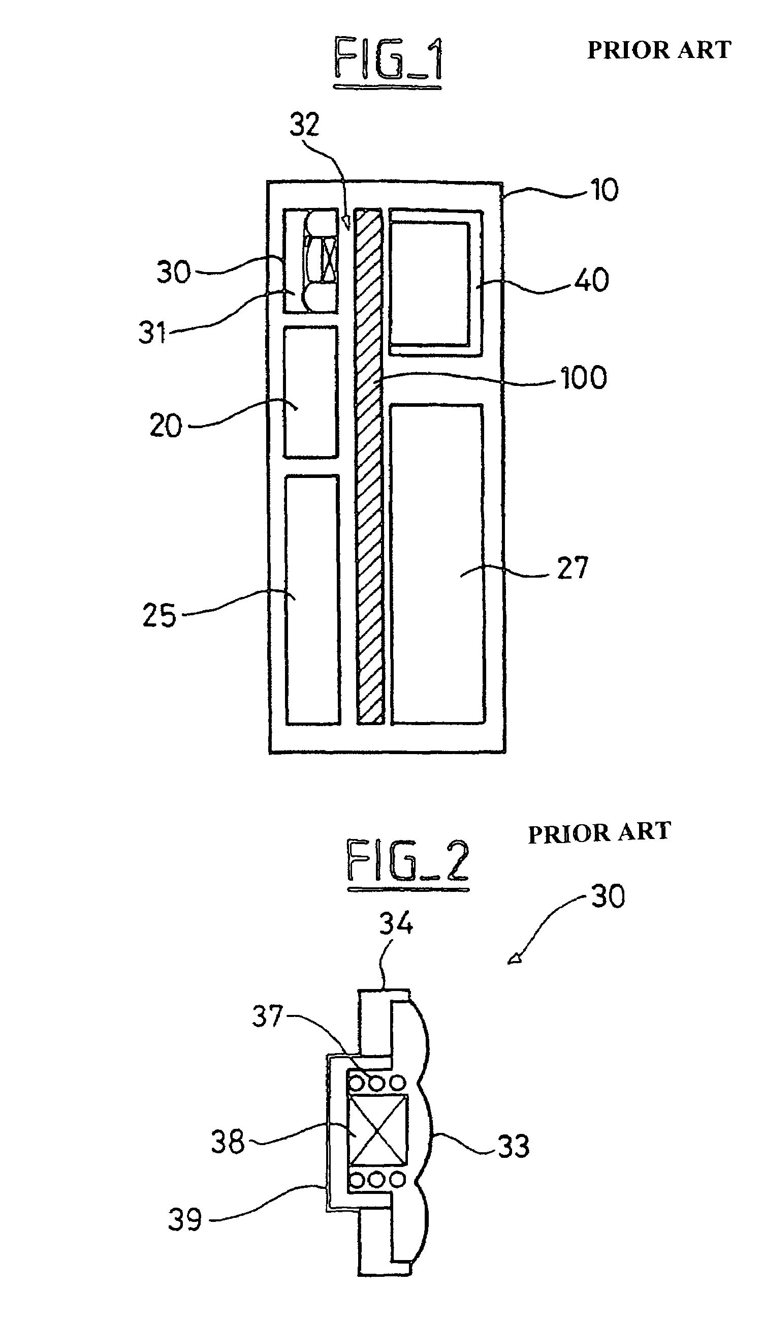
The volume for correct operation of the transducer cannot be reduced below a particular limit imposed by the loudspeaker function.

Method used


Image

  • Structural arrangement for a radio communication terminal incorporating a loudspeaker and an earpiece
  • Structural arrangement for a radio communication terminal incorporating a loudspeaker and an earpiece
  • Structural arrangement for a radio communication terminal incorporating a loudspeaker and an earpiece

Examples


Embodiment Construction

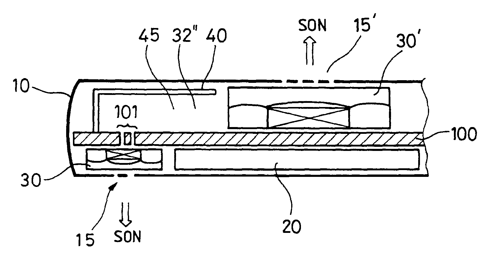
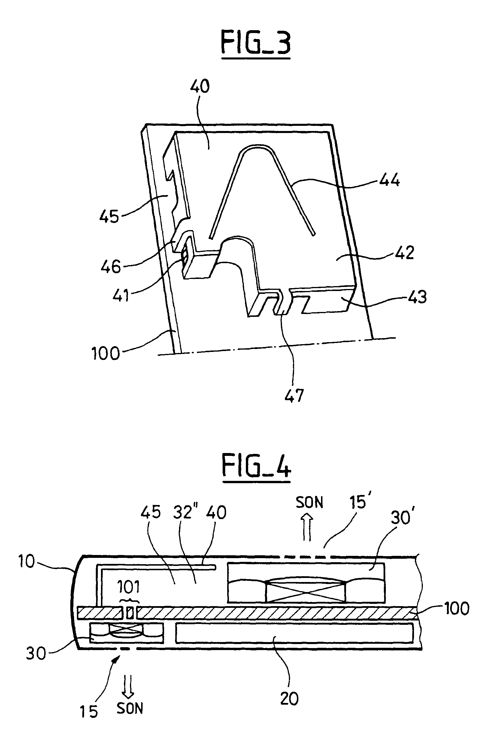
[0022]The invention uses two separate transducers for the earpiece and loudspeaker / ringer functions, respectively. FIG. 4 is a diagram showing one arrangement in accordance with the present invention.

[0023]As previously mentioned, the volume necessary for correct operation of the earpiece transducer is smaller than the volume necessary for correct operation of the loudspeaker transducer. An earpiece transducer 30 is therefore disposed on the front of the casing 10 of the radio communication terminal, above an enlarged screen 20, such as a liquid crystal screen, for example. A loudspeaker / ringer transducer 30′ is disposed on the rear of the casing 10 of the terminal, on the opposite side of the printed circuit card 100 to the first transducer 30.

[0024]In the conventional way, each of the transducers 30 and 30′ has a front acoustical cavity 31, 31′ and a rear acoustical cavity 32, 32′ as previously defined. According to an essential feature of the invention, the rear acoustical caviti...


PUM


Abstract

In a structural arrangement for radio communication terminals comprising a casing in which are disposed at least a first sound transducer having an earpiece function and a second sound transducer having a loudspeaker function, the two transducers being respectively connected to two opposite faces of a printed circuit card, and each transducer comprising at least one resonating membrane vibrating in a front acoustical cavity and a rear acoustical cavity. The rear acoustical cavities of the transducers communicate with each other via orifices formed in the printed circuit card to form a twin rear acoustical cavity.

Description

CROSS-REFERENCE TO RELATED APPLICATIONS[0001]This application is based on French Patent Application No. 02 10 969 filed Sep. 5, 2002, the disclosure of which is hereby incorporated by reference thereto in its entirety, and the priority of which is hereby claimed under 35 U.S.C. §119.BACKGROUND OF THE INVENTION[0002]1. Field of the Invention[0003]The present invention relates to a structural arrangement for radio communication terminals.[0004]2. Description of the Prior Art[0005]The current trend is to produce radio communication terminals of small size that are functionally ergonomic and user friendly. A radio communication terminal mainly comprises a casing in which equipment units are housed, in particular a radio transceiver unit comprising at least an antenna and a man-machine interface unit generally including a keypad, a screen and a sound transducer.[0006]The search for improved ergonomics and convenience has led to the antenna being accommodated inside the casing, for exampl...

Claims


Application Information

Patent Timeline
Patent Type & Authority Patents(United States)
IPC IPC(8): H04B1/38H01Q1/24H01Q5/00H01Q5/371H01Q9/04H04M1/03
CPCH01Q1/243H01Q9/0421H01Q5/371H04M1/03H04M1/035
Inventor DUFOSSE, STEPHANEVILLAIN, JEAN-CHRISTOPHEMENU, ERICLEBAUDOUR, YVES
Owner DRNC HLDG INC
Learn More