
Tilt hinge

a technology of tilting hinges and hinges, which is applied in the field of tilting hinges, can solve the problems of increasing the axial dimension of the friction hinge, the need for a large number, etc., and achieves the effects of reducing production costs, stable friction torque, and simplifying the structur

Inactive Publication Date: 2006-12-05
KATOH ELECTRIC MACHINERY
View PDF18 Cites 32 Cited by
  • Summary
  • Abstract
  • Description
  • Claims
  • Application Information

AI Technical Summary

Benefits of technology

The present invention provides a small-sized tilt hinge that can generate a necessary friction torque. The hinge includes a holder, a shaft, and a plurality of friction discs. The friction discs are held in the holder and can rotate and move in the axial direction. A resilient means is attached to the shaft to bring the friction discs into contact with each other. The friction discs can be made of different materials and have different stopper portions. The hinge can generate a stronger friction torque and is stable even after long-term use. The invention simplifies the structure and reduces production costs.

Problems solved by technology

Therefore, it has a problem of a need for a large number of the clips in order to obtain a necessary friction torque with a small diameter because the friction area of each of the clips is small.
In order to obtain a friction torque satisfying a development demand, for example, a friction torque of 100 kg / mm with a shaft with approximately 7 f, a larger number of the clips are required, which poses a problem of an increased axial dimension of the friction hinge.

Method used


Image

  • Tilt hinge
  • Tilt hinge
  • Tilt hinge

Examples


Embodiment Construction

[0030]Hereinafter, an embodiment of the present invention applied to a notebook personal computer will be described, but the tilt hinge according to the present invention is applicable to other small electronic equipment such as a laptop personal computer and so on.

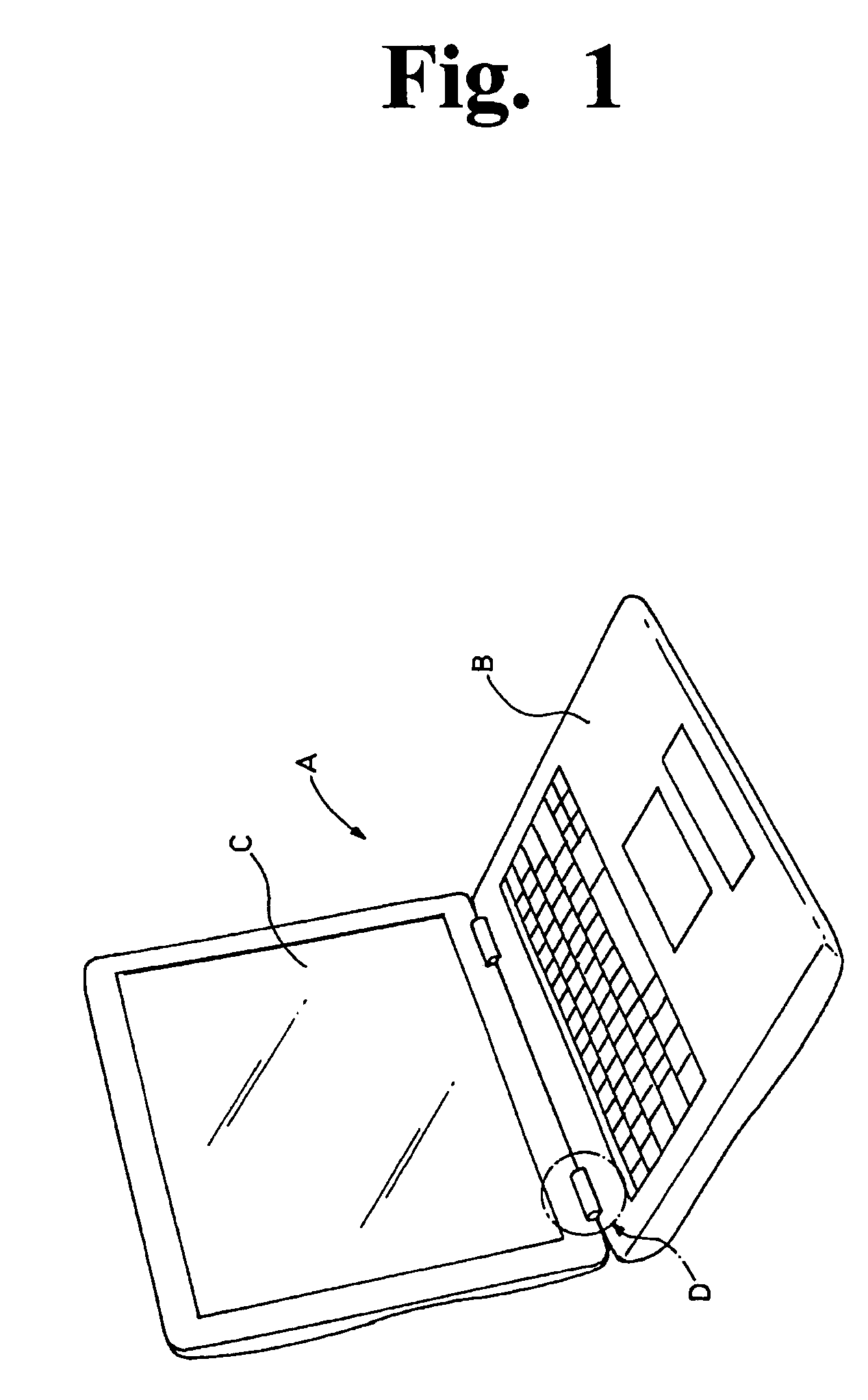
[0031]According to the drawings, FIG. 1 shows a notebook personal computer A using the tilt hinge according to the present invention. The reference symbol B denotes a keyboard main body and the reference symbol C denotes a display device. The tilt hinge according to the present invention, which is attached to a portion D, relatively openably / closably couples the keyboard main body B and the display device C. Typically, two tilt hinges are used.

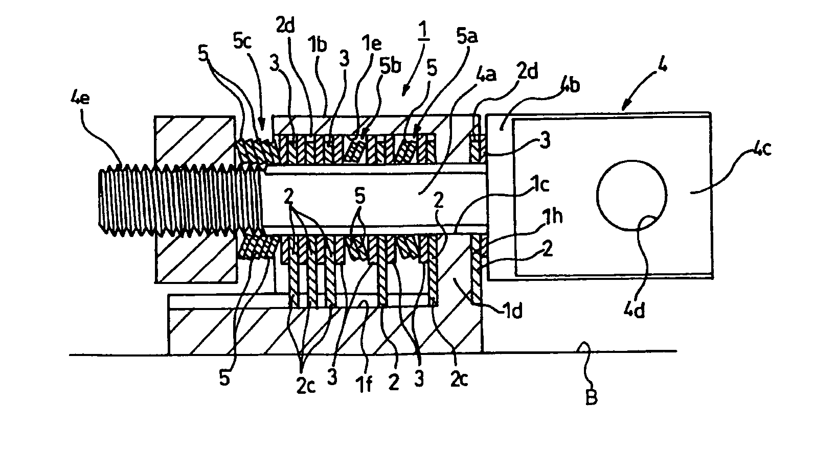
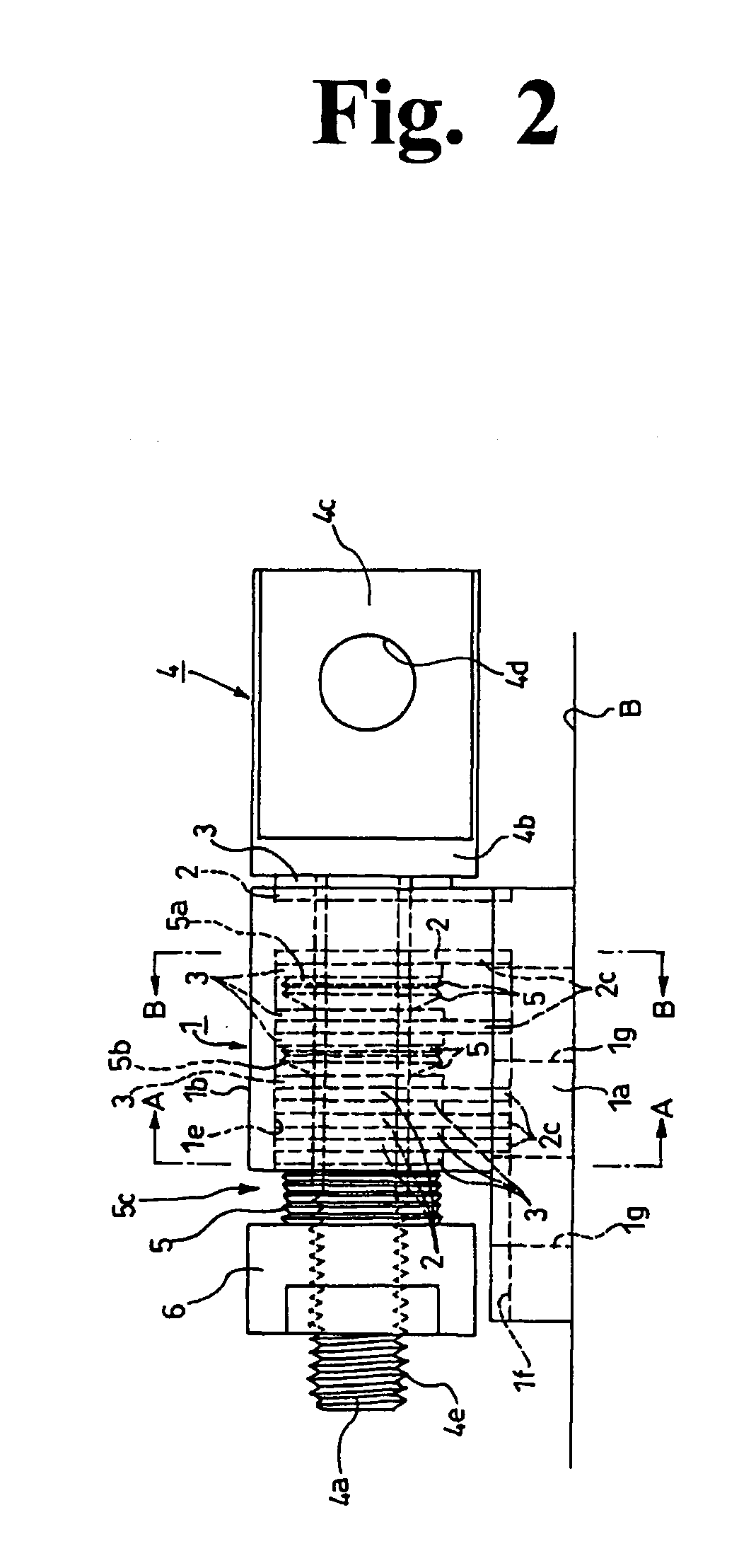
[0032]FIG. 2 to FIG. 5 show the structure of the tilt hinge according to the present invention. The reference numeral 1 denotes a holder attached to, for example, the keyboard main body B, which constitutes a first member, of the notebook personal computer A, and the holder 1 is com...


PUM


Abstract

In order to provide a tilt hinge small in size and diameter capable of generating a stable friction torque of approximately 100 kgf / mm, a hinge friction-rotatably coupling a first member and a second member that are relatively opened / closed includes: a holder attached to one of the first member and the second member; a shaft attached to the other one of the first member and the second member to be rotatable relative to the holder and immovable in an axial direction; a plurality of first friction discs restrained by the holder to be rotatable and movable in the axial direction, with the shaft being inserted through insertion holes thereof; a plurality of second friction discs interposed between the first friction discs to be movable in the axial direction with rotation thereof restrained by the shaft; and a plurality of disc springs and / or spring washers attached to the shaft so as to bring the first friction discs and the second friction discs to be in contact with each other by pressing the first friction discs and the second friction discs in the axial direction, wherein the disc springs and / or the spring washers are provided outside the holder in which the first friction discs and the second friction discs are stacked on each other and inside the holder.

Description

BACKGROUND OF THE INVENTION[0001]1. Field of the Invention[0002]The present invention relates to a tilt hinge suitable for use in friction-rotatably coupling a keyboard main body being a first member and a display device being a second member of small OA equipment, for example, a laptop personal computer and a notebook personal computer.[0003]2. Description of the Related Art[0004]A laptop personal computer or a notebook personal computer is composed of a keyboard main body and a display device openably / closably attached to the keyboard main body via a tilt hinge. Such a personal computer is folded into two in not use while in use, the display device is opened for use relative to the keyboard main body. The thickness and size as small as possible are demanded for these computers, and accordingly, a tilt hinge with a small diameter and a high friction function is demanded. As a tilt hinge satisfying such demands, one described in Translated National Publication of Patent Application ...

Claims


Application Information

Patent Timeline
Patent Type & Authority Patents(United States)
IPC IPC(8): E05D11/08F16C11/10F16C11/04G06F1/16
CPCG06F1/1681G06F1/1616E05D11/087E05Y2900/606Y10T16/5403Y10T16/540345E05Y2999/00G06F1/1613
Inventor MINAMI, TOSHIFUMI
Owner KATOH ELECTRIC MACHINERY
Learn More