Tractor for magnetic levitation traffic installation routing inspection rescue

A tractor and transportation technology, applied in the field of tractors, can solve problems such as wheel strength wear, difficulty in driving vehicles, difficulty in traction, etc., and achieve the effect of improving friction, large traction, and increasing friction area

Inactive Publication Date: 2014-11-12
成都金和工贸有限公司
6 Cites 7 Cited by

AI-Extracted Technical Summary

Problems solved by technology

[0003] At present, it is difficult to drive vehicles on the F rail row of the maglev transportation line, because the aluminum induction plate surface cannot be rolled except for the sliding surface, and because the friction surface of the wheels running on the sliding surface ...

Method used

Increase the loading drive wheel (6) that connects bogie (2) below its F rail (A) that is just the grooved surface (a2) formed by the two magnetic pole legs on the opposite side, and the loading is realized by hydraulic cylinder (8) , in order to...

Abstract

The invention discloses a tractor for magnetic levitation traffic installation routing inspection rescue. The tractor is composed of a bearing driving wheel (1), a loading driving wheel (6), a bogie (2), a tractor body (3), a power transmission system (4) and a driving braking system (5). The bearing driving wheel (1) walks on a sliding face (a1) of a rail F (A). The loading driving wheel (6) additionally walks inside a groove-shaped face (a2) opposite to the sliding face (a1) of the rail F (A), so that the friction area of the wheels and the positive pressure of the upper and lower wheels are increased, the frictional force is effectively improved, large traction is obtained, meanwhile, the interior of the groove-shaped face of the reverse face of the rail F is not affected by rain or snow or freeze weather, and it is better ensured that the larger traction is obtained.

Application Domain

CarriagesLocomotives

Technology Topic

Image

  • Tractor for magnetic levitation traffic installation routing inspection rescue
  • Tractor for magnetic levitation traffic installation routing inspection rescue
  • Tractor for magnetic levitation traffic installation routing inspection rescue

Examples

  • Experimental program(2)

Example Embodiment

[0020] Example one:
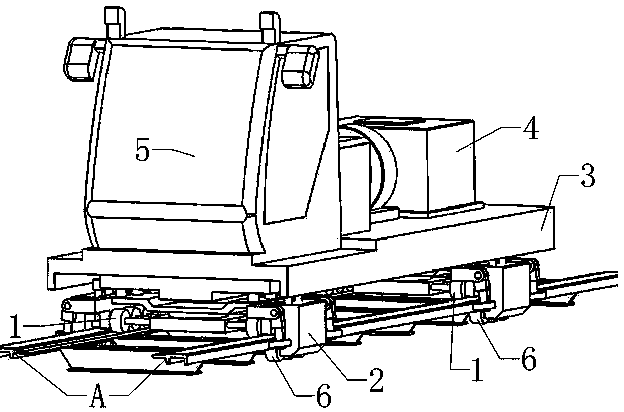
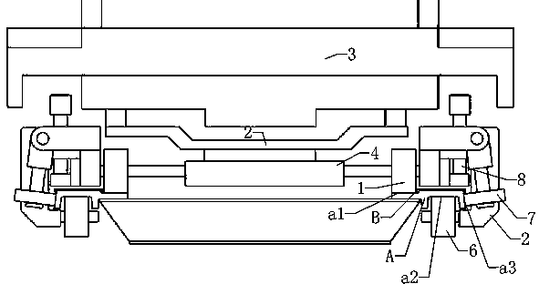
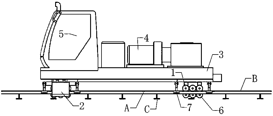
[0021] Such as figure 1 , figure 2 , image 3 , The tractor is running on the rail row composed of F rail (A) aluminum induction plate (B) and sleeper (C) on the maglev track line;
[0022] The towing vehicle runs on the sliding surface (a1) of the F rail (A) by carrying the driving wheels (1), and then supports the car body (3) through the bogie (2), and the power transmission system (3) is installed on the car body (3). 4) and driving brake system (5);
[0023] A loading driving wheel (6) connected to the bogie (2) is added to the groove-shaped surface (a2) formed by the two magnetic pole legs under the F rail (A), which is the opposite side, and the loading is realized by the hydraulic cylinder (8) to increase The friction area and positive pressure of the wheels are generally not affected in the groove-shaped surface on the reverse side of the F rail in rain, snow, and freezing weather, so it can still provide a stable and large traction;
[0024] The moment formed by loading the load driving wheel (1) and the load driving wheel (6) shall not affect the safety of the bolts connecting the F rail (A) and the sleeper (C) (the picture does not indicate the link bolt);
[0025] The power is driven by the internal combustion engine generator and the hydraulic motor of the hydraulic station. The hydraulic motor is directly installed in each drive unit (not detailed in the figure). It can also be powered by a rechargeable battery or directly installed with an on-board current receiver to be driven by electricity;
[0026] Couplers (not shown in the figure) are set on the front and rear of the tractor to link external vehicles, and the testing equipment can also be directly installed on the tractor;
[0027] The tractor is equipped with two front and rear bogies, and two front and rear guide wheels (7) are arranged on the outside of each bogie. The guide wheels (7) are controlled by the outer side (outside of the braking surface) (a3) ​​of the F rail (A) to achieve guidance ;
[0028] The guide wheels (7) are arranged in groups, each guide wheel group is composed of two front and rear guide wheels (7) with the same line center offset, and the distance between the axles is greater than the link seam of the F rail (A);
[0029] The guide wheel (7) can have a gap control with the guide surface (a3), or it can act elastically on the outer side (outside of the brake surface) (a3) ​​of the F rail (A), and its elastic force guides the bogie (2) in the line In the center position, guide deviation correction.

Example Embodiment

[0030] Embodiment two:
[0031] The first embodiment is usually used when a large traction force is to be obtained, such as pulling a heavy object, climbing a slope, etc., when the tractor is required to drive fast and does not require a large traction force, unlike the first embodiment, the driving wheel (6) is loaded It is separated from the F rail (A) surface, and the guide wheels are also guided by gap control or elastic guide.
[0032] It can be seen from the figure and the above installation steps that the tractor for patrol and rescue of maglev transportation installation of the present invention can provide a reliable and large traction effect.
[0033] All the features disclosed in this specification, or all disclosed methods or steps in the process, except for mutually exclusive features and/or steps, can be combined in any manner.

PUM

no PUM

Description & Claims & Application Information

We can also present the details of the Description, Claims and Application information to help users get a comprehensive understanding of the technical details of the patent, such as background art, summary of invention, brief description of drawings, description of embodiments, and other original content. On the other hand, users can also determine the specific scope of protection of the technology through the list of claims; as well as understand the changes in the life cycle of the technology with the presentation of the patent timeline. Login to view more.

Similar technology patents

Comfortable shooting training shoe

InactiveCN107772636AIncrease friction areaGuaranteed stabilitySolesInsolesBiomedical engineeringSlip resistance
Owner:TIANJIN TIANXING KESHENG LEATHER PROD

Novel and efficient brake

InactiveCN108488263AIncrease friction areaStable braking effectAxially engaging brakesBraking elementsPistonAgricultural engineering
Owner:广德盛源电器有限公司

Magnetic liquid shock absorber based on first-order buoyancy principle

ActiveCN112392889AIncrease friction areaImproved vibration damping effect and damping efficiencyMagnetic springsShock absorbersPhysicsMagnetic liquids
Owner:TSINGHUA UNIV

Friction clutch

InactiveCN103867593AIncrease friction areaReduce volumeFriction clutchesClutchFlywheel
Owner:杨勇

Immersed tunnel pipe joint thrust device

Owner:CHINA RAILWAY TUNNEL SURVEY & DESIGN INST

Classification and recommendation of technical efficacy words

  • Increase friction area
  • Increase friction

Clamping block of lead clamping device

InactiveCN102412522AIncrease friction areaReduce wire damageCable installation apparatusWave shapeEngineering
Owner:李刚

Braking device with transparent paper brake disc of cigarette packing machine

InactiveCN102530314AIncrease wrap angleIncrease friction areaWrapping material feeding apparatusDrum brakesCigarette packEngineering
Owner:CHINA TOBACCO GUIZHOU IND

Drill stem inner wall cleaner facilitating fixing of friction part

Owner:BEIJING LANDY GREAT EXPLOIT SCI & TECH DEV

Brake friction assembly for disk brake

InactiveCN101493125AIncrease friction areaLarge braking torqueAxially engaging brakesBraking elementsDisc brakeClutch
Owner:王文荣

Wear-resistant low-noise soft brake pad and preparation method thereof

InactiveCN112980392AIncrease friction areaIncreased longevity and safetyOther chemical processesFriction liningCrumb rubberFlake graphite
Owner:张豪

Blood collection system for collecting blood from a body part for diagnostic purposes

ActiveUS20070260272A1Increase frictionPrevent oscillationCatheterDiagnostic recording/measuringPuncturingBlood collection
Owner:ROCHE DIABETES CARE INC

Lead obstacle-crossing robot walking device

ActiveCN101574983AIncrease frictionIncrease crawl angleManipulatorCable installation apparatusHigh voltage transmission linesEngineering
Owner:CHINA ELECTRIC POWER RES INST +1
Why Eureka
Try Eureka